The air quality where I live has suddenly thrust itself into our consciousness. I regularly visit the Bay Area Air Quality Management District site and PurpleAir to find out what is happening in my neighborhood.
However, I wanted to know what the air quality was inside my house. Of course, I could just buy a PurpleAir sensor for nearly $200, but it turns out that the technology inside those sensors is something called the Plantower PMS5003. My friend Jeremy pointed me towards these ingenious little sensors draw in air and blow it in front of a laser, where dust particles scatter some of the light, which is detected by photodiodes. (Datasheet here) For various reasons you’ve read online, this is not the same as the “gold-standard” technology that EPA PM sensors use, but studies by some scientists suggest it’s not bad. And it’s cheap. You can get this module from Adafruit for $40 or on eBay for even less. I bought mine from an eBay seller for $20, but it came without a break-out board, making wiring a bit more difficult, but not too hard. It’s only three wires after all!
Thing is, the module is doing the heavy lifting, doing all the signal processing, but it’s not a complete system by itself. You need a computer to do something with the data.
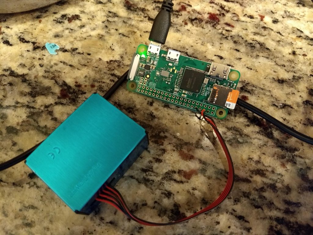
I found that the Raspberry Pi Zero W makes a nice little companion for the PMS5003. The Pi is powered by a USB adapter, and has a 5V pin from which you can steal the necessary power for the sensor. You can send the transmitted serial data from the sensor right into the UART0 receive pin of the Raspberry Pi. That plus a little bit of software, et voila, a simple sensor platform.
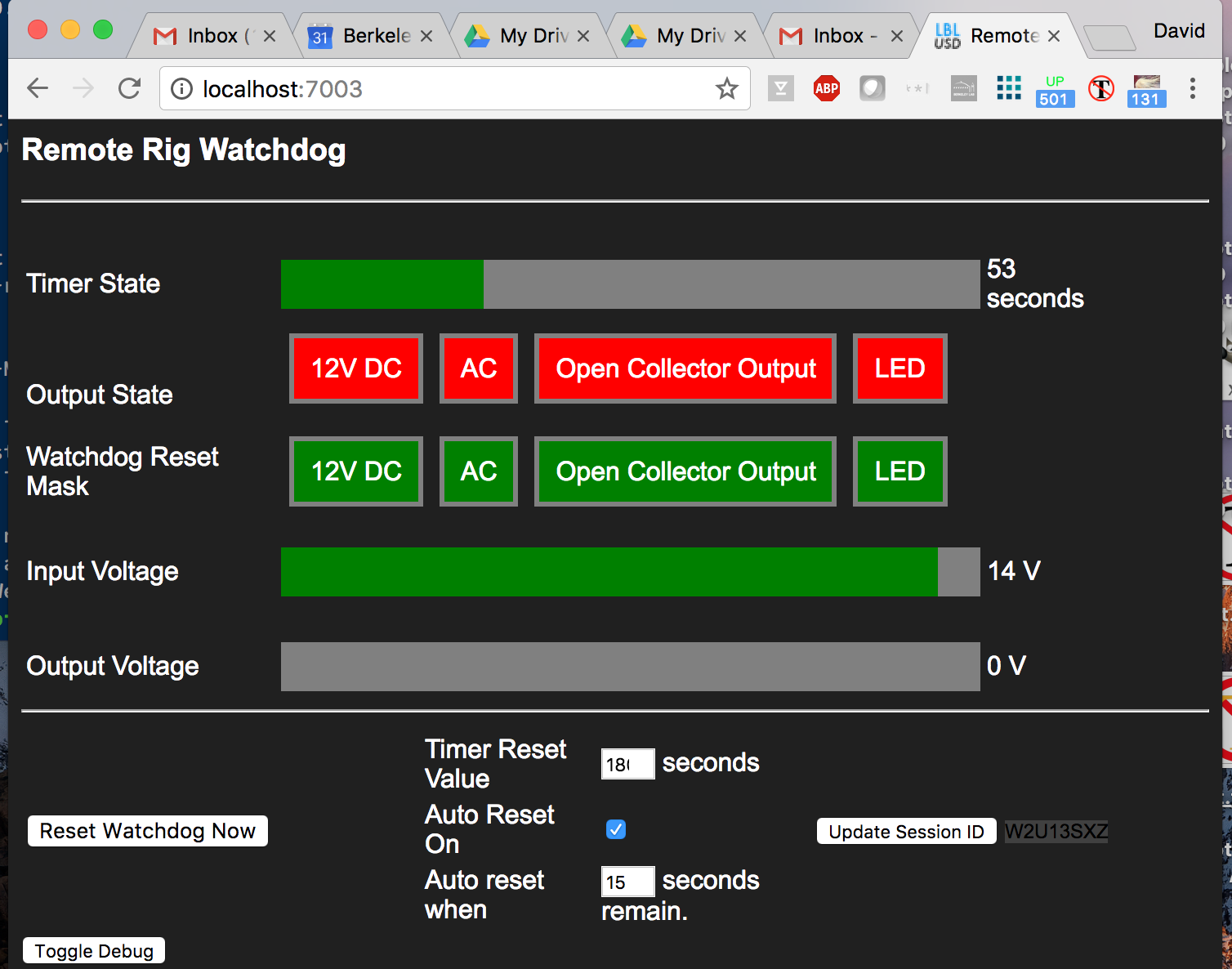
At first, I coded mine just to write the results, every second to a .csv file that I could load into a spreadsheet. But the copying and pasting quickly got old, so I decided to make a little webserver instead. Mine is set up on my home wifi and I can access it from my computer or phone just by going to its web address. It presents the data in various levels of time averaging: the first graph is second by second, then minute by minute, hour by hour, and day by day.
It’s a simple enough project that I think just about anybody could do.
I like to program in interpreted languages because development is fast and easy, and I think duck typing is Just Fine. But I also like the speed and efficiency of object code compiled from carefully written C or C++ that written with some regard to How Computers Actually Work.
So, from time to time, when I have a medium-sized project that benefits from flexibility but also needs some high performance computation, I use the ability of the scripting language to load and run native object code.
Back in ancient times I did this with Tcl. In slightly less ancient times, I used Perl. Perl has a cool set of modules called Inline::* that let you put source code for a compiled language mixed right in with the Perl code. It would then rebuild and link that code when you ran the Perl script and would cache the object code to save startup time on subsequent runs. It was brilliant, but I don’t code in Perl much anymore because all the serious programmers tell me “Perl is Considered Harmful.” (That is, most folks who pay me don’t want to see Perl code. Shrug.)
So I decided the other day to experiment with the binary interfaces to languages I use nearly every day: NodeJS and Python. I also included my old friend, Perl.
The test library to bind: the “fractizer”
I used a simple bit of C code I wrote awhile back for a parallel computing demo as my test target. (Relevant files are native/fractizer.[ch].) Until now, I have used it in a standalone executable that I call via fork from a simple Node.JS server application. The code computes fractals. It’s not rocket science, but it has just enough interface to be a half-decent experiment: a few functions, a struct, pointers, and an array. These are the basic elements you’d need to bind any library.
I worked on NodeJS first because my application already used it, and I thought it would be cool to avoid the fork() that was part of the existing demo.
Try 1
Node has a native binary interface, part of the V8 engine. V8 is under constant improvement, and they make no promises about long-term API or ABI compatibility. Instead, they have a (promised) more stable wrapper interface called N-API, so that you can move compiled objects between Node versions. It took me about an hour to figure out how to use N-API on my little functions. It would have taken less time had the documentation been better, particularly with examples that include a few non-trivial things like passing complex types to and from Node. But I got it working. The wrapper code looked like this:
It’s mostly straightforward, using various functions to create and access Javascript objects. I had to write a function to convert between a node Object and my configuration struct. This is a theme in all three languages I tried, and I think it’s lame. There should a utility that reads a header file and does this for me.
Note that the code returns something called a TypedArray. This is a cool thing. It lets you use a real pointer to memory in your compiled code but access is directly without a copy/conversion in Node. This, I’m pretty sure, helps avoid a copy of a potentially big array. It also avoids the size bloat of a similar length array of full-blown Javascript objects.
Try 2
Node has an interesting execution model. There is a single main thread, but you can take advantage of multiple additional threads for activities that might block or just take a long time to compute. Doing so also lets you avail yourself of extra CPU cores to run those long-running tasks while the main thread soldiers on. Taking advantage of this means making your code asynchronous.
Getting that to work well took more time than I care to admit, but I did ultimately succeed. Again, the documentation sucked, particularly regarding how you marshal data across the script/binary boundary and between main and subthreads. In the end, not much wrapper code was really needed, but figuring it out was not fun — lots of segfaults in the interim.
This is what the async wrapper looked like (I also switched to a C++ wrapper around the native API. This cut down a bit on typing but I’m not sure it’s a better than the raw C functions, especially if you don’t want to use C++ exceptions:
Still had to write that struct setter function, though.
To use this in Node, you need to compile it (obvs). Basically, you install node-gyp from npm and then call:node-gyp configure build. You will need a configuration file for gyp that is pretty simple:
Anyway, that worked fine, but I did not enjoy the experience. One thing I do not like is that all the dealing with Node objects still needs to be done in the main thread. So you must be in the main thread to convert any input arguments to the form your native code will understand, then run your native code in its own thread, and then when it is done, it calls back to the main thread, where you’ll provide more code to unspool your native types back to Javascript objects. I wish some of that prep/unprep could be done in the async part, so that you maximize the performance of the main loop. In my case, converting a C array into a Javascript Array takes runtime I’d rather not have in the main event loop. Alas, I was not able to figure out how to do this, though I suspect this is possible and I was just too dumb to figure it out.
Next at bat: Python
Anyway, after the Node experience and because of the one-way-to-do-it philosophy of the Python community, I just assumed Python would be a pain in the ass, too. It turns out, no, Python isn’t so bad. In fact, for Python, using the ctypes library, I could wrap my existing library code without writing any more C code — the entire wrapper could be done in Python! I didn’t have to do anything to the source to adjust my native code.
I did tell Python all about my structs, but in return I got automagically created object accessors, so fair trade.
In theory, if you already have a .so built, you needn’t even compile anything at all. (Actually, I did have to add “extern C” because the ABI is C-only and my original code was in a cpp file even though it was basically just C.
Anyway, the new Python module looked like this:
import ctypes

class fparams_t(ctypes.Structure):
    _fields_ = [
        ('max_iters', ctypes.c_ushort),
        ('escape_val', ctypes.c_double),
        ('x_min', ctypes.c_double),
        ('x_max', ctypes.c_double),
        ('y_min', ctypes.c_double),
        ('y_max', ctypes.c_double),
        ('x_pels', ctypes.c_ushort),
        ('y_pels', ctypes.c_ushort),
        ('x_tile', ctypes.c_ushort),
        ('y_tile', ctypes.c_ushort),
        ('type', ctypes.c_ubyte),
        ('do_julia', ctypes.c_ubyte),
        ('jx', ctypes.c_double),
        ('jy', ctypes.c_double),
        ('algo',ctypes.c_void_p),
]


class Fractizer(object):
    def __init__(self):
        self.fr = ctypes.cdll.LoadLibrary('./fractizer.so')
        self.params = fparams_t()
        self.fr.set_default_params(ctypes.byref(self.params))

    def getParams(self):
        return self.params

    def showParams(self):
        self.fr.showParams(ctypes.byref(self.params))

    def compute(self):
        output_len = self.params.x_pels * self.params.y_pels
        output_ary_t = ctypes.c_ushort * output_len
        output_ary = output_ary_t()
        poutput_ary = ctypes.pointer(output_ary)
        self.fr.generate_fractal(ctypes.byref(self.params),poutput_ary)
        return output_ary

    def showResult(self,ary):
        olines = [];
        for j in range(self.params.y_pels):
            x = [ary[i + j*self.params.x_pels] for i in range(self.params.y_pels)]
            y = ['{0:4}'.format(q) for q in x]
            olines.append(' '.join(y))
        return '\n'.join(olines)


if __name__ == '__main__':
    # example usage
    f = Fractizer()
    f.getParams().x_pels = 20
    f.getParams().y_pels = 20
    f.showParams()
    result = f.compute()
    print(f.showResult(result))
Of the languages I tested, only Python asked me to build the code myself, but I think that’s reasonable, as their main idea is that you are binding an existing library anyway:
Not so bad. I think it would have been cool if Python could have read the C header file and generated the parallel Python type for the parameters rather than me having to create (and hardcode) it myself, but I guess it’s about par for the course. However, at least I did not have to write accessor functions.
Overall, I was impressed with the Python. I was also able to run Python in threads and create separate instances of my wrapped function and it all seemed to go just fine.
Olde Tymes’ Sake: Perl
I finished with Perl, because I remembered it being so easy. I remembered incorrectly. All the building and linking stuff is handled by Inline::C, but if your library uses its own types, Perl needs just as much help as the other languages. You need to tell it about any structs you might have to use, and provide accessor functions for them.
Telling Perl about the types is straightforward. You create a typemap to tell it these are pointers to things it doesn’t understand:
Basically, I told it that there are these things called fparams_t and cp_t, and that Perl will be managing pointers to them but doesn’t really need to know about their innards. A more complex typemap could have created accessors for me automaticaly, but I find it easier just to let Perl treat the structs as opaque and provide access with my own routines. Usually, only a subset of the members of a struct will require access from Perl. I also had to add types for uint16_t and uint8_t because the built-in type system doesn’t know the <stdint.h> aliases for basic types. Kind of annoying, since the error messages were not helpful at all.
There is a library on CPAN, Inline::Struct, that reads struct definitions in header files and automatically create typemaps for them. I haven’t gotten it to work yet, but I am corresponding with the author and I think we can get it to work eventually. In the meantime, I have to handle the structs myself.
Anyway, this is an entire Perl script including the wrapper code and a quick-n-dirty example run:
I didn’t evaluate the performance of these various bindings. I assume they are all similar. The one exception might be the synchronous binding in Node.JS. I think that one has the potential to be faster because the same array used by the C code can be wrapped and use directly by NodeJS as a TypedArray. This avoids a copy of the entire output buffer contents that all the other versions do either implicitly of explicitly.
Conclusion
Binding compiled/compilable code to your favorite dynamic language gives you the benefits of both, with the overhead of having to learn just a bit more about the inner guts of the scripting language than you’d prefer. The process is more or less the same in the three languages I tried, but you see the philosophies vary.
Because there is no standard C++ ABI, all of the languages force you to use “extern C” C++ code. The exception is the C++ wrapper code for Node N-API, which sort of does the inverse. You include a head that use C++ to wrap the the N-API C functions; it works because you are compiling the wrapper.
Something I did not try is taking objects from languages other than C and C++ and binding them to the scripting languages. I am assuming that if those languages use a C style ABI that I can just link those and pretend they came from a C compiler.
Addendum: SWIG
Those of you who have been down this road before will ask, what about SWIG? The “Simple Wrapper Interface Generator” is a tool designed to look at your source and automatically generate wrappers for popular languages. SWIG has been around for a very long time. The last time I tried to use it was >10 years ago and I remember the experience as not great:
Getting SWIG installed and built was not trivial at the time, particularly on Windows.
I had to learn about SWIG and its special .i language for specifying interfaces
I had to make changes to my code so that SWIG could understand it
I had to apply some manual tweaks to the wrapper code it generated. You can do this with their language, but it is still basically you coding in the target language’s API.
In the intervening decade, some of this is fixed and some of this is most decidedly not fixed. On the plus side, it’s easier to install than it used to be. But on the downside, SWIG macros are as arcane as ever, and they do not save you from having to know how your scripting language interface API works — which to my mind is the whole point of SWIG.
This is what a usable input file to SWIG looked like for my project (for Perl):
%module fractizer
%{
#include "fractizer.h"
%}

%include "fractizer.h"

%inline %{
    unsigned short *make_obuf(size_t s) {
        unsigned short *p = malloc(sizeof(unsigned short) * s);
        return p;
    }
    void free_obuf(unsigned short *p) {
        if (p) free(p);
    }
    SV *bufToArray(unsigned short *buf, size_t len) {
        AV *av = newAV();
        for (size_t i=0; i<len; i++) {
            av_push(av, newSVuv(buf[i]));
        }
        return newRV_noinc((SV*)av);
    }
%}
The first part is not so bad: just include the C header file. But things go downhill from there:
I needed to provide routines for creating and freeing buffers that were not in my library. That’s reasonable, as this code is still all in “C land.”
To see the contents of that buffer in the scripting language, I needed to provide a routine to do that. And that routine is written using the primitives provided by the scripting language — the exact thing you’d hope SWIG was designed to do for you. So now I have invested time in learning SWIG and I still need to know how $scripting_language works under the hood. Why bother?
Finally, SWIG didn’t understand stdint types, either, so I had to change my code to use olde fashioned names. Maybe that’s just a Perl typemap issue.
It also took me a little while to figure out how it wrapped my code and how to call it. The right answer is like this:
#!/usr/bin/perl -w
use lib '.';

use fractizer;

my $width  = 200;
my $height = 100;

my $params = fractizer::fparams_t->new();
fractizer::set_default_params($params);
$params->swig_x_pels_set($width);
$params->swig_y_pels_set($height);

fractizer::showParams($params);

my $obuf = fractizer::make_obuf($params->swig_x_pels_get() * $params->swig_y_pels_get());

fractizer::generate_fractal($params,$obuf);

my $output = fractizer::bufToArray($obuf,$params->swig_x_pels_get() * $params->swig_y_pels_get());

fractizer::free_obuf($obuf);

# ... then display the results
In short, my take on SWIG hasn’t changed: it introduces the complexity of its own little macro language and you are not really shielded from the details of your scripting language’s implementation.
I’ve been interested in energy efficiency for a long time. A big part of understanding energy efficiency is understanding how devices use power, and when. Because of that, I’ve also long wanted an AC power meter. A cheap one. A decent one. A small one.
What is an AC Power Meter
An AC power meter is an instrument that can tell you how much juice a plug-load device is using. The problem is that measuring AC power is a bit tricky. This is because when dealing with AC, the current waveform that a device draws does not have to be in phase with the voltage. A load can be inductive (lagging) or capacitive (leading), and the result is that the apparent power (Volts RMS * Amps RMS) will be higher than the real power. It gets worse, though. Nonlinear loads, like switch-mode power supplies (in just about everything these days) can have current waveforms that literally have no relation to the voltage waveform.
As a result, the way modern AC power meters work is to sample the instantaneous current and voltage many times a second, in fact, many times per 60 Hz AC cycle, so that the true power can be calculated by calculating the “scalar product” of the voltage and current time series. From such calculation, you can get goodies like:
Real power (watts)
Apparent Power (VA)
Imaginary/Reactive Power (VAR)
phase angle
power factor
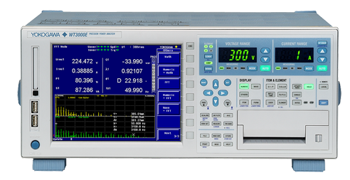
Instruments that do this well are expensive. For example, this Yokogawa WT3000E is sex on a stick as far as power meters go, but will set you back, I think more than $10k. I used one when I was at Google, and it was a sweet ride, for sure.
This is on my Christmas list, in case you’re wondering what to get me.
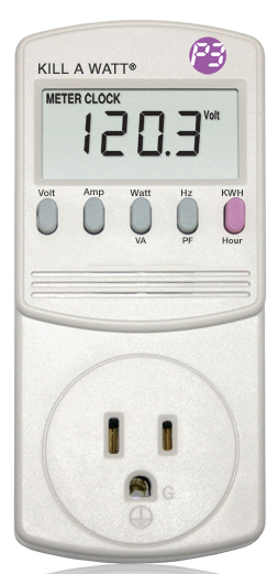
Cheap but effective.
On the other hand, you can get a Kill-A-Watt for $40. This is cheap and functional, but is not capable of logging data, and is totally uncalibrated. They claim 0.2% accuracy, though? My experience with them says otherwise.
Over the years I’ve built a couple of attempts at a power meters. One used a current transformer and a voltage transformer going into the ADCs of an Arduino. It sort of worked, but was a mess. Another time, I built a device that used hall-effect sensors to measure current, but I didn’t measure voltage at all. This really couldn’t measure power, but you could get an indicative sense from it.
Let’s Do This – Hardware Design
So, a few months ago, I resolved to build a proper power meter. I did a search for chips that could help me out, and lo and behold, I came across several “analog front end” chips that have all the circuitry you need to measure AC power. They do the analog to digital conversion, all the math, and give you a simple digital interface where you can query various parameters.
I settled on the Atmel ATM90E26. Reasonable basic accuracy of 0.1% built on 16b analog-to-digital converters, and best of all, about $2 in quantity 1. Furthermore, they have an app note with a sample design, and it seemed simple enough.
So I started designing. Unfortunately, I had various conflicting goals in mind:
Safety: like the McDLT, I want the hot to stay hot and the cool to stay cool. This means total isolation between the measurement side and the control side.
Small, so it can be put inside a small appliance.
A display, so I could read power data directly
An interface to a Raspberry Pi so that I could log to a μSD card, or send it via WiFi to the Internet
A microprocessor of its own to drive the display and do any real-time processing needed
An internal AC to DC power supply so that the device itself could be powered from a single AC connection.
Ability to measure current by way of sense resistor, current transformer, or some combination of both.
Ability to get reasonably accurate measurement of very small loads (like < 1W) so that I can make measurements concerning vampire power. One way to do this wile keeping precision, is to build a unit with a high value shunt resistor, which I can do if I’m rolling my own.
Some of these desires conflict with each other, and I made several iterations on the computer before making my first board. I ended up jettisoning the LCD and building the thing around the RPi Zero. This was primarily to make the board compact. If I wanted a display I could plug one into the Pi! I also initially went with an outboard AC/DC converter mostly because I just didn’t want to fuss with it.
Power and Isolation
In a device that’s intended to live inside a plastic box, I probably wouldn’t bother with isolation at all. The whole circuit could “ride the mains.” But because this is supposed to be a tinker-friendly board, I wanted to be able to touch the RPi without dying. Usually, this is done with something simple like optoisolators to provide galvanic isolation for data signals. But this board presented another challenge. The power measurement chip needs to be exposed to the AC (duh, so it can measure it) but it also needs DC power itself to operate.
How to power the chip and maintain isolation? This could be done with a simple “capacitive dropper” supply (simple, inefficient, sketchy), or with an isolated DC-to-DC supply (pricey and or fussy), but when I added up the optoisolators I’d need plus the DC-DC supply, I realized that a special purpose chip would be nearly cost effective and would be a lot less fuss. So I chose the AduM5411, a nifty part from Analog Devices that can forward three digital signals in one direction, one digital signal in the other direction, and provide power across the isolation barrier. And it was only like $6.
Only problem is, the AduM5411 is so good it is pure unobtanium. I’m not even sure the part really exists in the wild. So I switched to the Texas Instruments ISOW7841, a very similar part in all respects, except for the fact that it costs $10. This is the most expensive part in my BOM by far. But I have to admit, it is super easy to use and works perfectly. (As an aside, these chips do not work on optical principles at all, but on tiny little transformers being driven at high frequency. Kind cool.)
Okay, so the AC/hot part of the board is powered from the DC side of the board. But how is the DC side powered? In the first iteration, I did it from a USB connector via a 5V wall-wart.
Current Measurement
In order to measure power, the measurement chip needs to be able to measure the voltage and current, simultaneously and separately. Voltage is pretty easy. Just use a resistor network to scale it down so you don’t blow up the ADC. Current can be done one of two ways. One is to measure the voltage drop across a calibrated resistor. The resistor obviously needs to be able to handle a lot of current and it will have to be a small value to keep the voltage drop reasonably, or else the device you’re measuring will be unhappy. The current sense resistor should also have a low temperature coefficient, so that its value doesn’t change much as it warms up.
The other approach is to use a current transformer. CTs are nice in that they provide isolation, but they are large and cost a few bucks compared to the few pennies for the resistors. I did an iteration with space for a CT on the board, but later punted on that. I did leave a place where an external CT can be plugged into the board. I may never use it, though.
The Microcontroller
In this design, an Atmega 328p microcontroller sits between the Pi and the ATM90E26. It is connected to the ATM90E26 by a SPI bus and to the Pi by an I2C bus. Originally, I had thought the Atmega would have to poll the power chip frequently and integrate the total energy, but that was because I did not read the ATM90E26 data sheet closely enough. It turns out that chip can does all the math itself, including integrating energy, and so the processor was just sitting there doing conversion between I2C and SPI. I honestly could not come up with anything else useful for the Atmega to do.
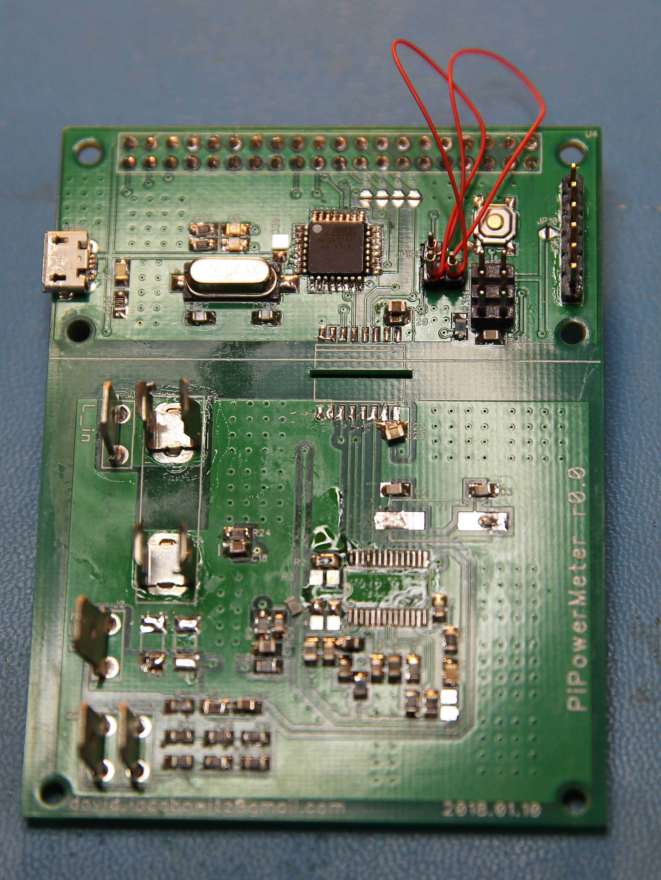
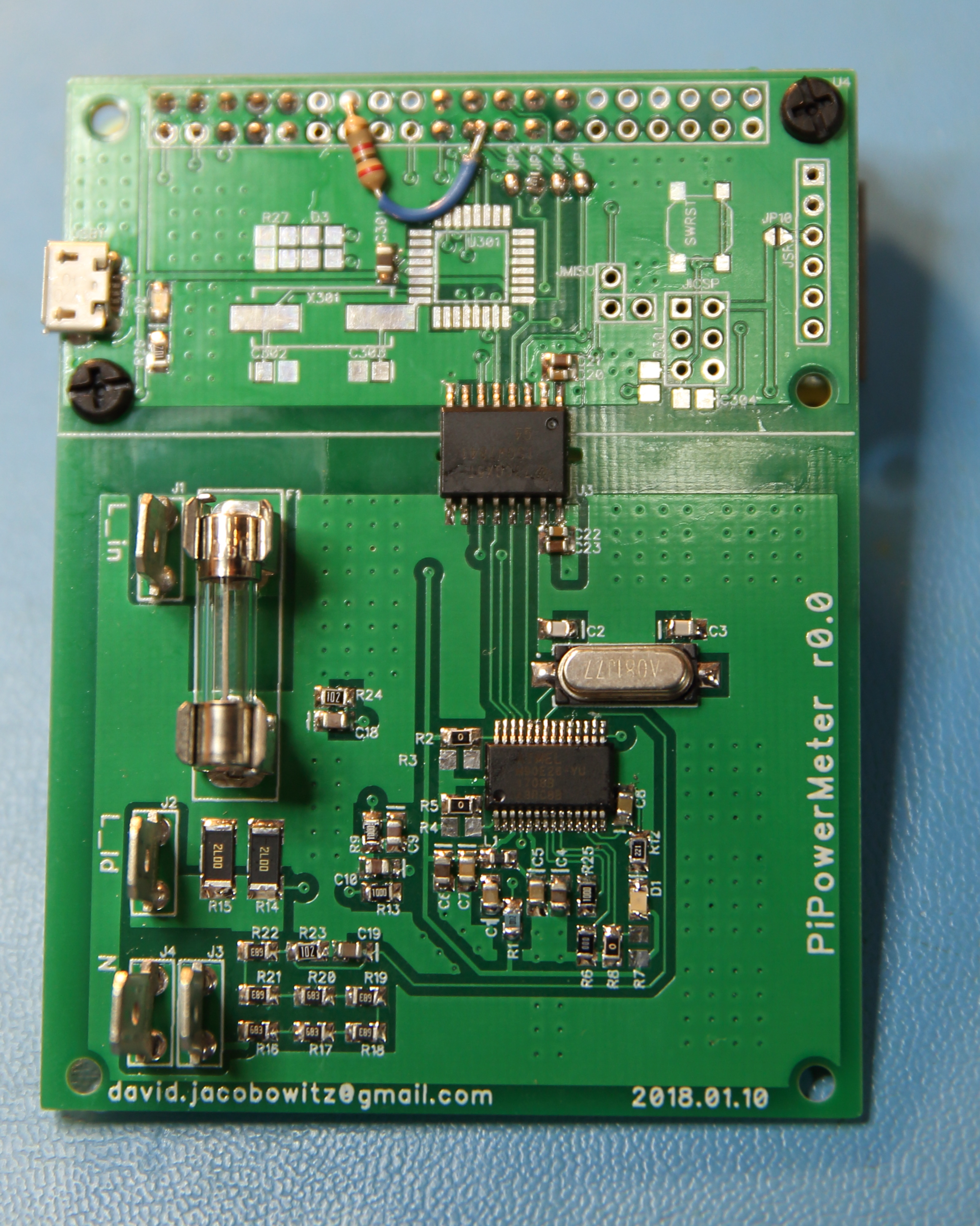
This is the board after I scavenged it for some of the more expensive parts.
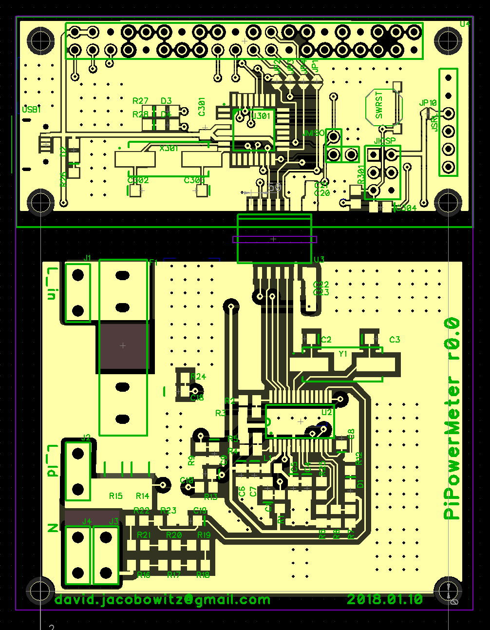
The first design I had fabbed.
Anyway, the good news was that this design worked straight away — hardware wise, though it turned out to be more work than I wanted to get the Atmega to do the I2C/SPI forwarding reliably. And I didn’t even need it.
Ditch the processor!
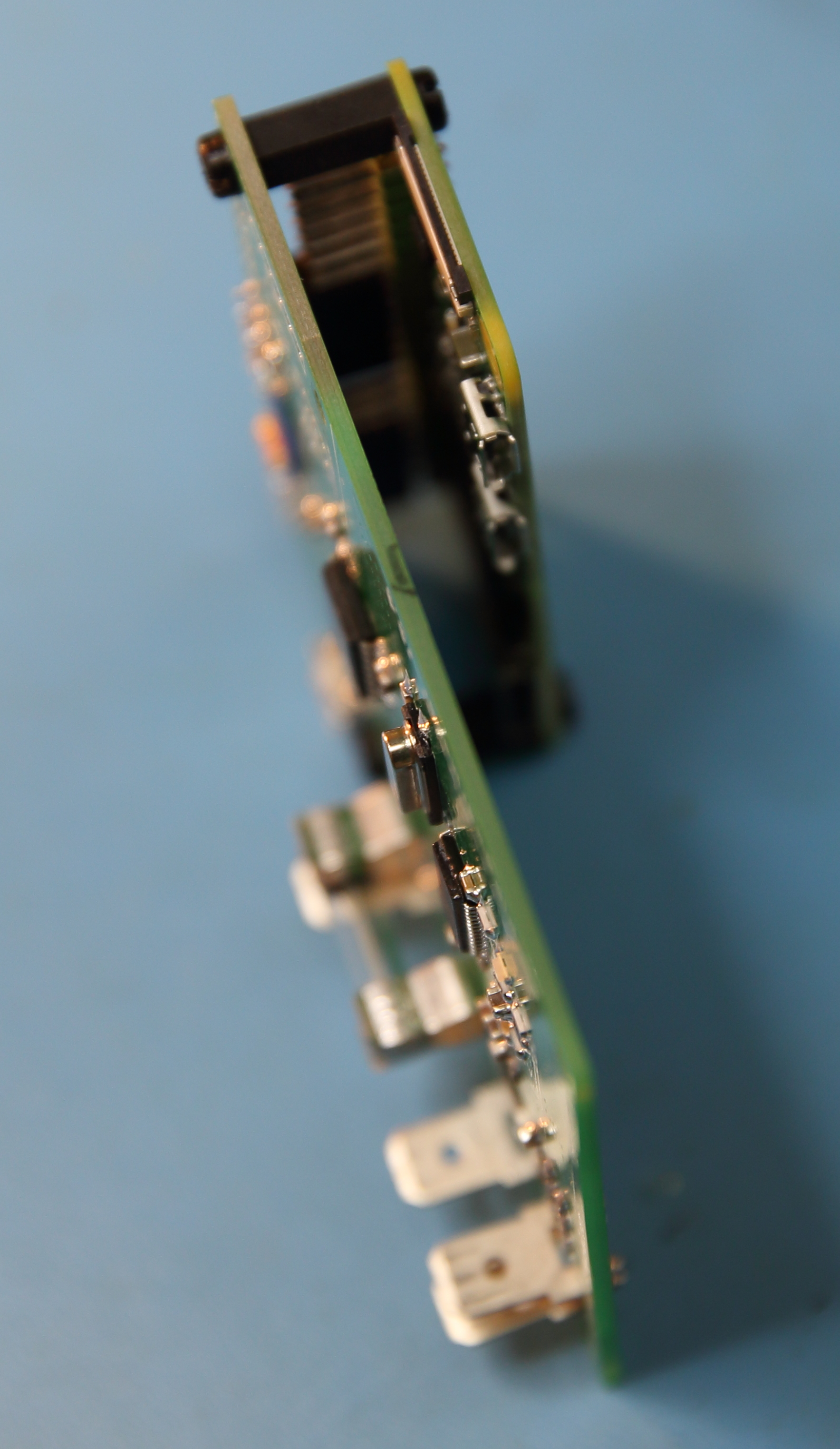
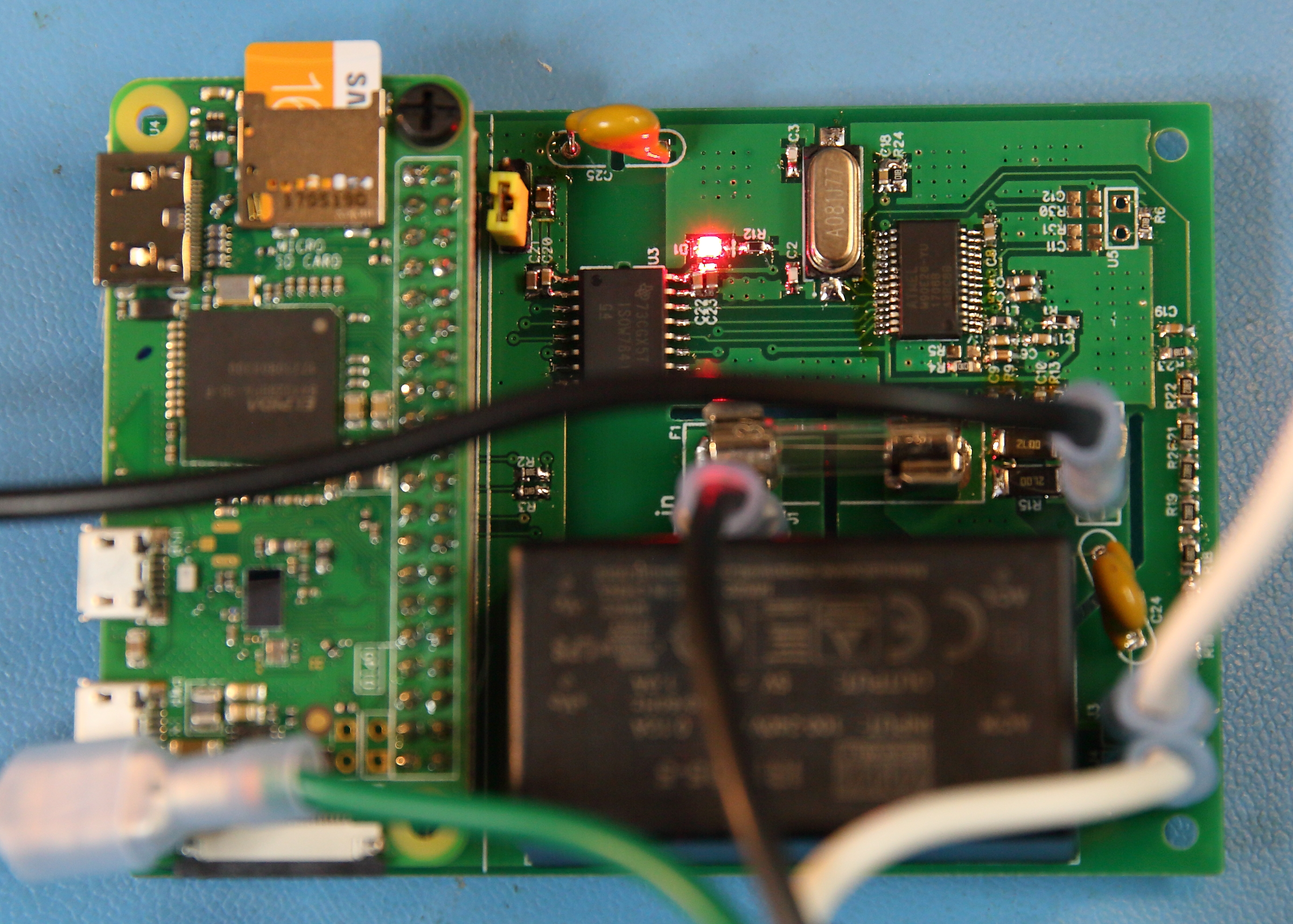
So, using the same PCB, I made some simple hacks to bring the SPI bus pins from the measurement chip to the RPi header. I also had to add a voltage divider so that the 5V MISO signal would not destroy the not-5V-tolerant MISO pin on the RPi. The hacked board looked like this.
Look ma, no intermediary microprocessor
Board on its side, so you can see how the RPi rides along.
The RPi communicates with the power measurement chip through the TI isolation chip, and des so reliably and much faster than I2C, so I was glad to realize that I didn’t need that intermediary processor in the mix at all.
This board could be pressed into service as it was, but it has a couple of issues:
First, the orientation of the Pi relative to the board saves a bit of space, but does so at the cost of having all the Pi connectors face down towards the “hot” side of the board.
Second, powering the DC side of the board from the USB jack proved more annoying to me than I had anticipated. It really just bugs me to have to plug an AC measuring device into a separate wall-wart. So I knew I’d design in a PSU. I chose a MeanWell IRM-05-05 PCB mount 5V PSU.
Third, this board lacked cut-outs to provide extra creepage for high voltage parts of the board that would be (or could be) at high relative voltage from each other. I think the distances were probably adequate, and it’s not like I was going for a UL listing or anything, but I still wanted slots.
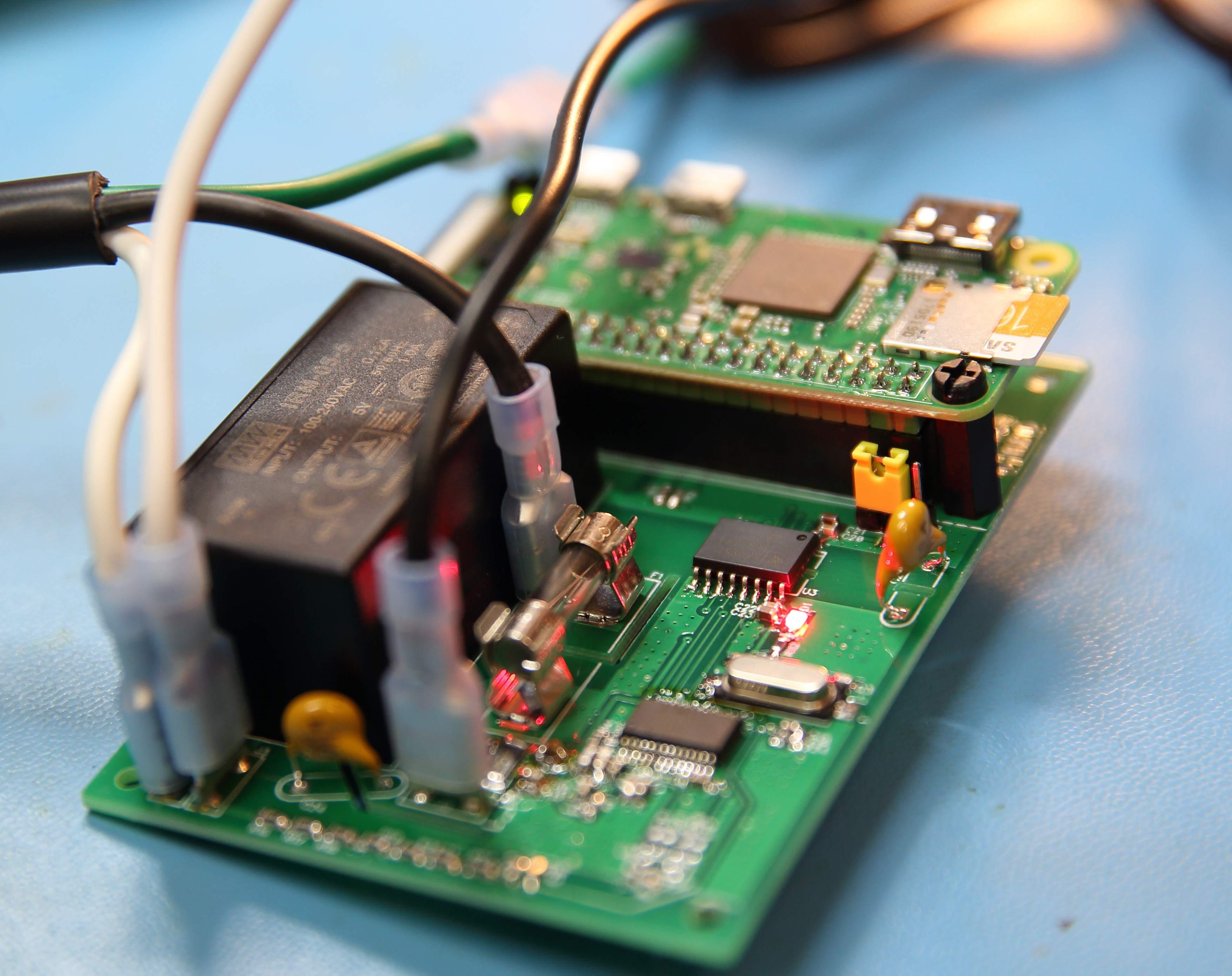
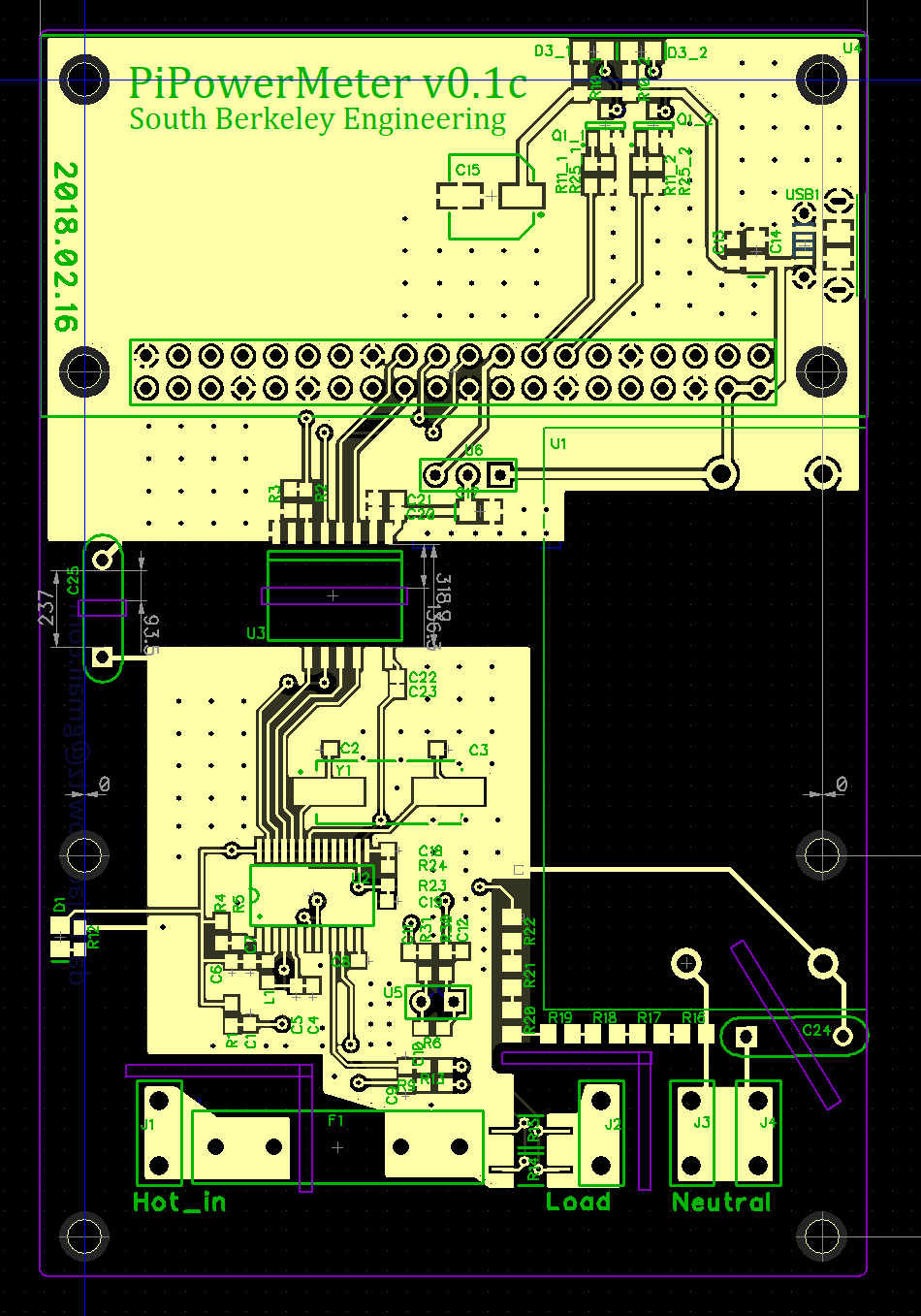
So, I redesigned the board and waited a month for them to arrive from China even though I payed for expedited shipping. The new board looks like this. Some of the space where the processor had gone I replaced room for LEDs, in case I want to blink some lights.
Looking much better. Notice the Pi has all its ports pointing away from the AC. Also, the Pi is on top rather than underneath.
Better layout, no processor
I really need to clean off that flux.
So that is just about it for the hardware.
One last spin.
As it turns out, I will spin this board one more time. The main reason is that I want to expand it a bit and move the mounting holes to match up with a suitable enclosure. I will probably use a Hammond RP-1127 — it’s exactly the right width for an RPi.
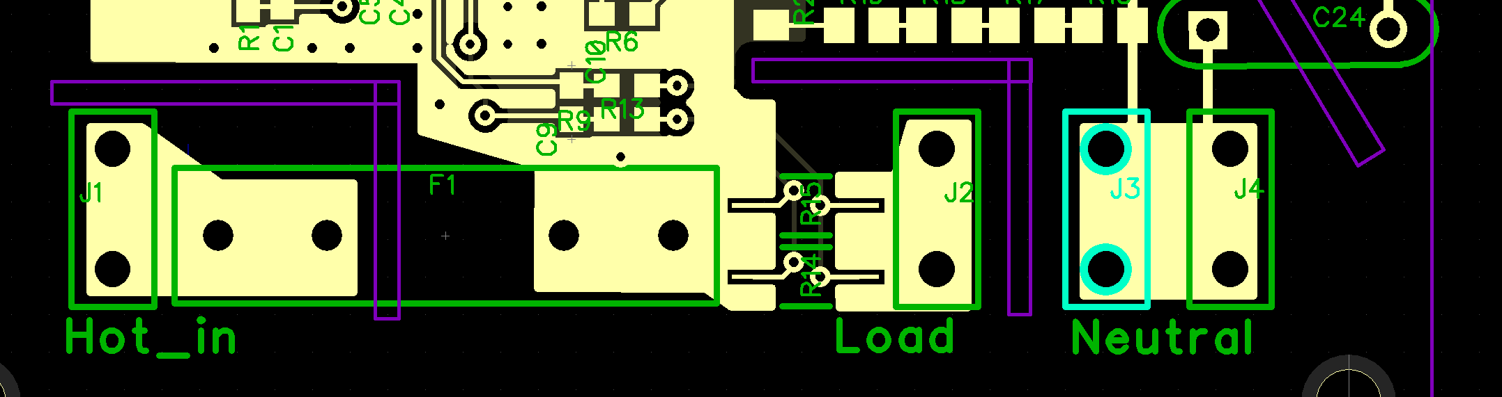
The way the current measurement is to measure the current across the sense resistor. This resistor is reasonably accurate and temperature stable, but the solder and copper traces leading to it are not, and current flowing in them will cause a voltage drop there, too. This drop will be small, but the drop across the 0.001 Ω sense resistor is small, too! So, to get the most accurate measurement, I try to measure the voltage drop exactly at the resistor pads, preferably with connections to the resistor that have no current in them. This i what Kelvin connections are.
In the case below, I achieve something like this by splitting the pads for the resistor into three pieces. The top and bottom conduct test current across the resistor, and a small, isolated sliver in the middle measure the voltage. There is no current in that sliver, so it should have no voltage drop.
The result should be better accuracy and thermal stability of the current measurements. The Kelvin connection for the current measurement looks like this. The sense resistors go betwen the right terminal of the input fuse and the tab marked “load.” The resistor landing pads are split and a separate section, in which no current will flow is for the voltage measurement.
Fake four-terminal resistor
Calibration
An instrument is only as good as its calibration, and I needed a way to calibrate this one. Unfortunately, I do not have the equipment to do it properly. Such equipment might be a programmable AC source, a high-accuracy AC load, and perhaps a bench quality power meter. What I do have access to are reasonably accurate DMMs (Fluke 87V and HP 34401A). The former is actually in cal, the latter, well, a million years ago, I’m sure.
I calibrated the voltage by hooking the unit up to the AC mains in my house and measuring the voltage at the terminals and adjusting a register value until the reported voltage matched my meter. For current, I put a largeish mostly non-inductive load on the system (Toast-R-Oven) and measured the current with my DMM and adjusted the register until the current matched.
Calibrating power is harder, and I really don’t have the right equipment to do it properly. The ATM90E26 allows you to also set up an energy calibration separate from the voltage and current measurements, and I think it is their intention that this be done with a known load of crappy power factor. But I don’t have such a load, so I sort of cribbed a guess at the energy calibration based on my voltage and current measurements of the toaster oven. This probably gets me close for resistive loads, but is not good enough for loads with interesting power factor. Unfortunately, the whole point of an AC power meter is to get this right, so in this important way, my meter is probably importantly compromised.
The result is that this is probably not a 0.1% instrument, or even a 1% instrument, but I guess it’s good enough for me… for now. I’ll try to think of ways to improve cal without spending money for fancy equipment or a visit to a cal lab.
Okay, so now about software
One of the reasons I like working with the Raspberry Pi, is that I get a “real”, and “normal” linux operating system, with all the familiar tools, including text editors, git, and interpreted programming languages like python. Python has i2c and SPI libraries for interacting with the the RPi hardware interfaces, so it was not a big deal to create a “device driver” for the ATM90E26. In fact, such a device driver was pretty much just an exercise is getting the names of all the registers and their addresses on one page. One nice thing my device driver does is convert the data format from the ATM90E26 to normal floats. Some of the registers are scaled by 10x or 100x, some are unsigned, some are signed two’s complement, and some have a sign bit. So the device driver takes care of that.
I also wrote two sample “applications.” The first is a combination of an HTTP server app and a client app running on the meter that forwards info to the server, and the server can display it in a web browser.
The other application is simpler, but in a way, more useful: I have the RPi simply upload samples to a Google Sheet! It’s very satisfying to plug in a logger and then open a Google Sheet anywhere and see the data flowing in every few seconds.
Results
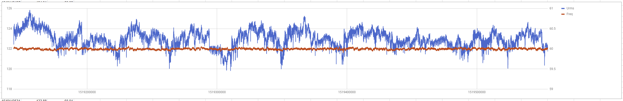
So far, I’ve been able to things like log the voltage and frequency of the mains every second for the past week. I plan to deploy a few of these around the house, where I can see how various appliances are actually used.
Here’s a picture of the voltage and frequency as measured in my work shed for most of a week starting on 2/20/2018. The data are in 5 second intervals.
You can see a diurnal voltage pattern, and the frequency is rock solid
Design Files
I have not decided if I’m going to open-source this design yet, so I’m going to keep the hardware files to myself for the time being. There is also a liability concern, should someone take my stuff and manage to burn his house down or kill himself.
But you can see my github repo with the software. Not too much documentation there, but I think the file atm90e26.py should be reasonably self-explanatory as a simple Python-based wrapper for an ATM90E26 connected to a Pi via SPI.
Future Directions
Better calibration
Better WiFi performance when device is inside a metal appliance (external antenna)
Switchable current ranges. Maybe with relays swapping in difference sense resistors.
An interesting aspect of my job is that I am sometimes asked to do weird stuff. I like weird stuff, so this is a good.
Recently, I was asked to build “turkey detector.” You see, my boss wanted a demo that we shows that we can help scientists deploy sensors, and collect and process the data from them. Furthermore, we wanted a demo that would show machine learning in action.
Oh, did I mention that there are a lot of wild turkeys strutting around this campus?
So we figured, hey, let’s deploy some cameras, take pictures, send them to a turkey classifier model, and put the results on website. What could be easier?
There are some interesting constraints:
not having a lot of spare time to do this (have other more pressing responsibilities)
minimal resources
no wired electrical or network access in the most turkey-friendly outdoor areas
I added a few constraints of my own, to make things more interesting:
the cameras need to be able to withstand the weather and operate without physical interaction for a long time. Not that we need these cameras to stay up forever, but a real camera trap should be able to last.
don’t use proprietary hardware or software — everything open source (well, almost everything, as you’ll see)
Commercial, already-built camera traps exist, but they, as far as I know, do not sync up with wifi and do not keep themselves charged. You have to go out to change batteries and collect your memory card. Bah.
Electronic Hardware
For the computer, I went with the Raspberry Pi Zero W after starting with a Raspberry Pi 3. These are ARM-based circuit board with built-in WiFi and a special port for attaching a camera. The “3” has a multi-core process and more ports. The Zero is slower but smaller and uses about 1/2 to 1/3 the power of the Pi 3.
I like the RPi platform. It’s reasonably open, simple to use (its Raspbian OS is basically like any Debian-based Linux), and crazy cheap. The Pi Zero W is $10! For the camera I used the companion “PiCamera 2” designed to go with the RPi. It’s an 8Mpixel tiny phone camera jobbie, fixed focus and fixed aperture, about $30.
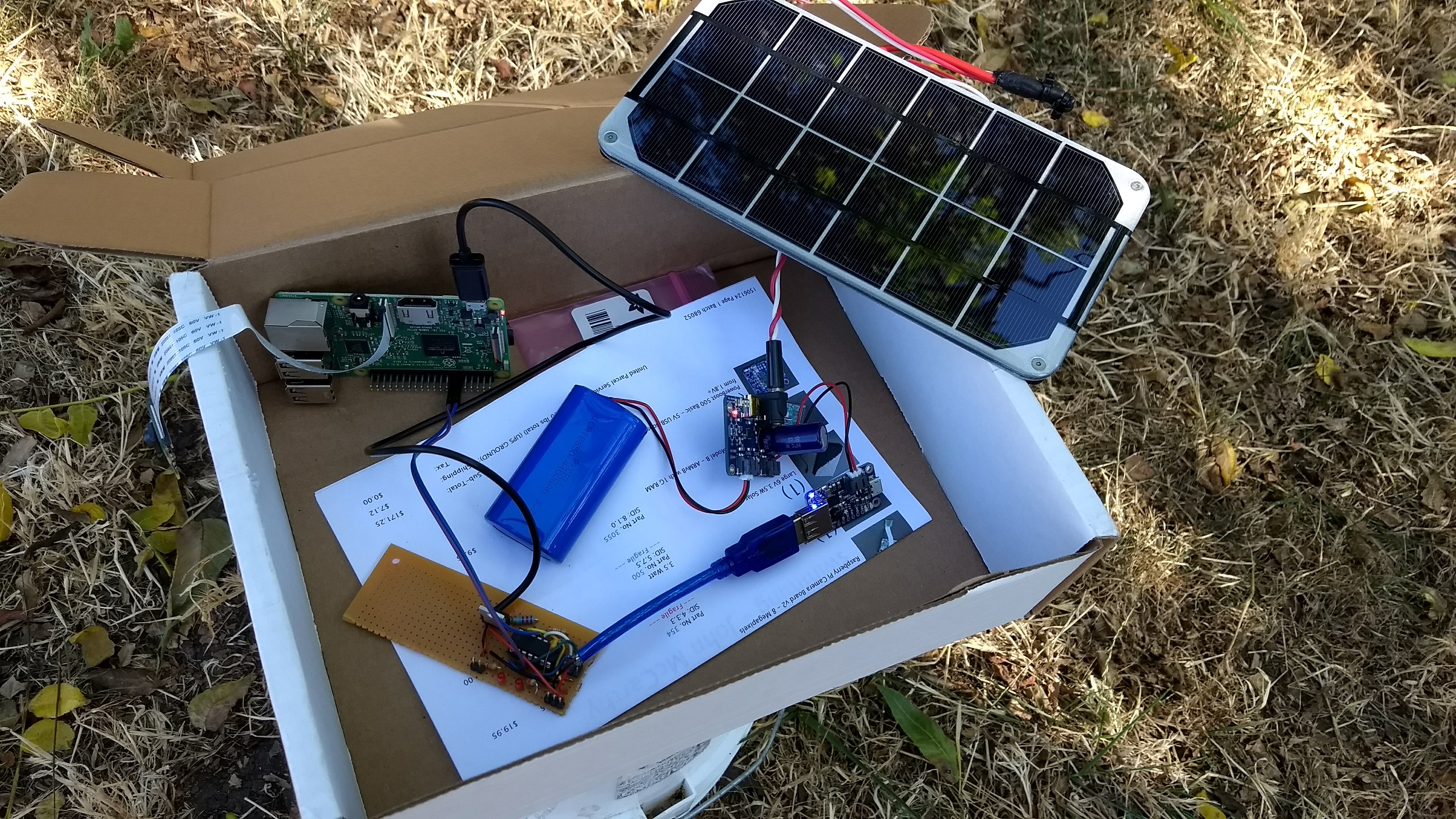
Getting a hard-wired power to the unit would be out of the question, so this needs to work from battery. I ended up using a single LiPo cell, 3.7V 4.4Ah. This is enough to power the Pi for about a day without any new charge, but it’s not enough to go two days or run overnigh. To charge, two small solar 6V solar panels, 3.5W each would do that job. The panels require a charge controller to adjust the panel output to the battery. Also, the Pi requires 5V, and the battery only puts out ~3.5-4V, so a boost converter to make a stable 5V is also required. The panels were a huge ripoff, at $11/Wp and I’m not thrilled with the cost and quality of the charge controller and boost converter either, but they do work.
Here’s a picture of all the kit, in a cardboard box in my backyard. Well, almost all the kit. An RPi 3 is pictured, which I moved away from because of its power use. Also, there are two panels in the operating camera.
On a sunny, or moderately sunny day, there is enough power to operate the camera and charge the battery. On a cloudy day, the battery drains slowly, or doesn’t drain, but doesn’t charge either.
Either way, I needed a solution to deal with night. As it happens, the RPi has neither a clock to keep time while it’s off, nor a means of turning itself off or on. Because of this, I built a small companion board with an Attiny84A microcontroller connected to a FET transistor. The Attiny actually turns the RPi on in the morning and off at night, thus saving precious power. The Attiny itself does not draw all that much power, so can run continuously.
The communications protocol between the processors is primitive, but functional. The RPi has two signal wires going to the Attiny. One is pulsed periodically to tell the Attiny that the RPi is still functioning. If the pulses stop, the Attiny waits a few minutes and then turns of the power, then waits a few more minutes and turns it back on again. The other pin is used to tell the Attiny that the RPi wants to be turned off. After getting a pulse on this pin, the Attiny shuts down the RPi for an hour. The RPi also gets a low battery signal from the boost converter, which it can use to determine that it should shut itself down (cleanly) and then request to the Attiny that it be turned off. I try to avoid shutting down the Pi willy-nilly, because the filesystem might be corrupted.
I said that the RPi has no clock. When it boots it tries to connect to a network and then get the time from a time server. Once it has done this, it can proceed with normal operation and keep good time while it’s running. If it can’t get the time from the Internet, it asks to be shut down again to try again later. The RPi decides it’s time to be shut off for the night by comparing the time with sunset, as calculated from a solar ephemeris library.
All said, the power system I came up with is basically just barely adequate, and even when the battery simply cannot run the system, the unit turns off in a controlled fashion and, assuming the battery eventually charges again, the Pi will reboot eventually and get back up.
A next gen camera (already in the works) will have a much bigger battery and charging system. On e-bay, one can get 20W or 25W panels kits with charge controller for about $1/Wp for the panel, as they should be. These charge controllers are designed for 12V lead-acid batteries, though, so I’ll need to use a nice alarm system type AGM battery. A nice thing about most of these charge controllers is that they tend to have USB charger ports, so I do not need the 5V buck controller. Everything is large, though, and setting up a rack to hold the large panel is a problem I have not yet solved. But overall, the lesson I’m learning is that everything is easier when you have power to spare.
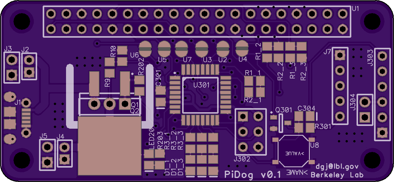
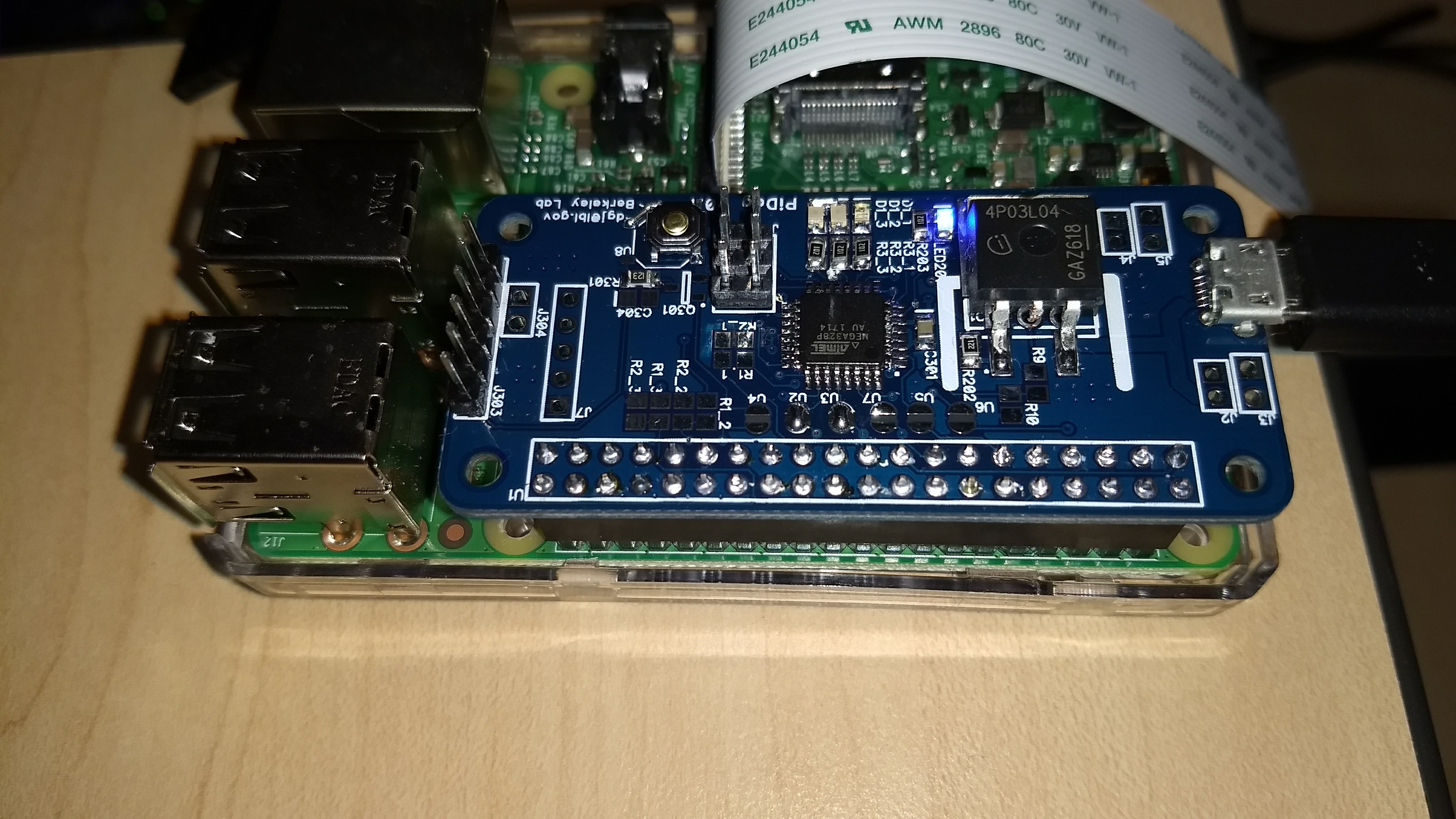
The Attiny watchdog circuit works pretty well, but it was a hand-made hack on a proto board and the communication “protocol” is pretty lame. Since deploying the first camera, I have designed a board to replace my hack on subsequent cameras. The new board is powered by an Atmega328p, which is the same processor that the Arduino uses. I am abandoned the Attiny because I want to use i2c to communicate and the 328p has an i2c hardware module. You can bit-bang (that is, do it in software) i2c with the Attiny, but the RPi i2c controller has a bug which makes it unreliable with slower i2c devices. Anyway, the i2c interface allows transferring more complex messages between the processors, like “shut down in 3 minutes and then wait 7 hours 47 minutes before starting me up again.” The new board just plugs into the RPi and you plug the power cable into it rather than the RPi, so it’ll be unfussy to setup.
The board design:
Finished board in action:
Software
The software side of things was comparatively simple and only took a few hours to get up and running. (I’ve spent a lot more time on it since, though!) On the RPi, a python script snaps pictures every few seconds. It compares each image to the previous one it took, and if they are sufficiently different (that is, something in the scene has changed), it sends the image to a server. If the picture is the same as the last, the server is only pinged to let it know the camera is still alive. Hours can go by without any pictures being sent.
On the server, the images are analyzed using the ML model to determine if there are turkeys. I did not have a sufficient training set of turkey / non-turkey images to build a custom model, so I am using a pre-cooked Amazon AWS model called Rekognition to ID the poultry. This is my one concession to proprietary “cloud” stuff. Rekognition is idiot-proof, so maybe no the best demo of ML chops, but, eh. One thing about using AWS is that it costs money, so the optimization of not sending redundant images is important for not racking up a huge bill.
The server is written in NodeJS, and receives and processes the pictures as well as hosting a simple website. All communication is JSON messages over REST over HTTPS.
When it comes to software, I have an ongoing war with myself. I like to keep things simple for me (not so much typing) but also like to keep things actually simple (not reliant on large, complex frameworks and libraries that bring in zillons of dependencies and things I don’t understand and can’t easily maintain). To this end, I tried to stick to libraries available from apt and even then, not too much. On the RPi, I used the standard camera and GPIO libraries that come with Raspbian, and installed the python3 modules requests and scikit-image. (I chose not to use OpenCV, which is a shame, because it looks cool. But there is no pre-built package and I didn’t want to build it from source. Building complex things from source on the Pi takes a loooong time, trust me!) On the server, I used Node with Express and I think no other modules — though to be fair, package management in Node is a breeze anyway.
Oh, and for course there is some code running on the Attiny and there is some HTML and Javascript for the client side — so this little project encompasses four or five separate languages, depending on how you count. I think I could have done the server in Python, but I’m still grappling with concurrency in Python. Maybe one day I’ll figure.
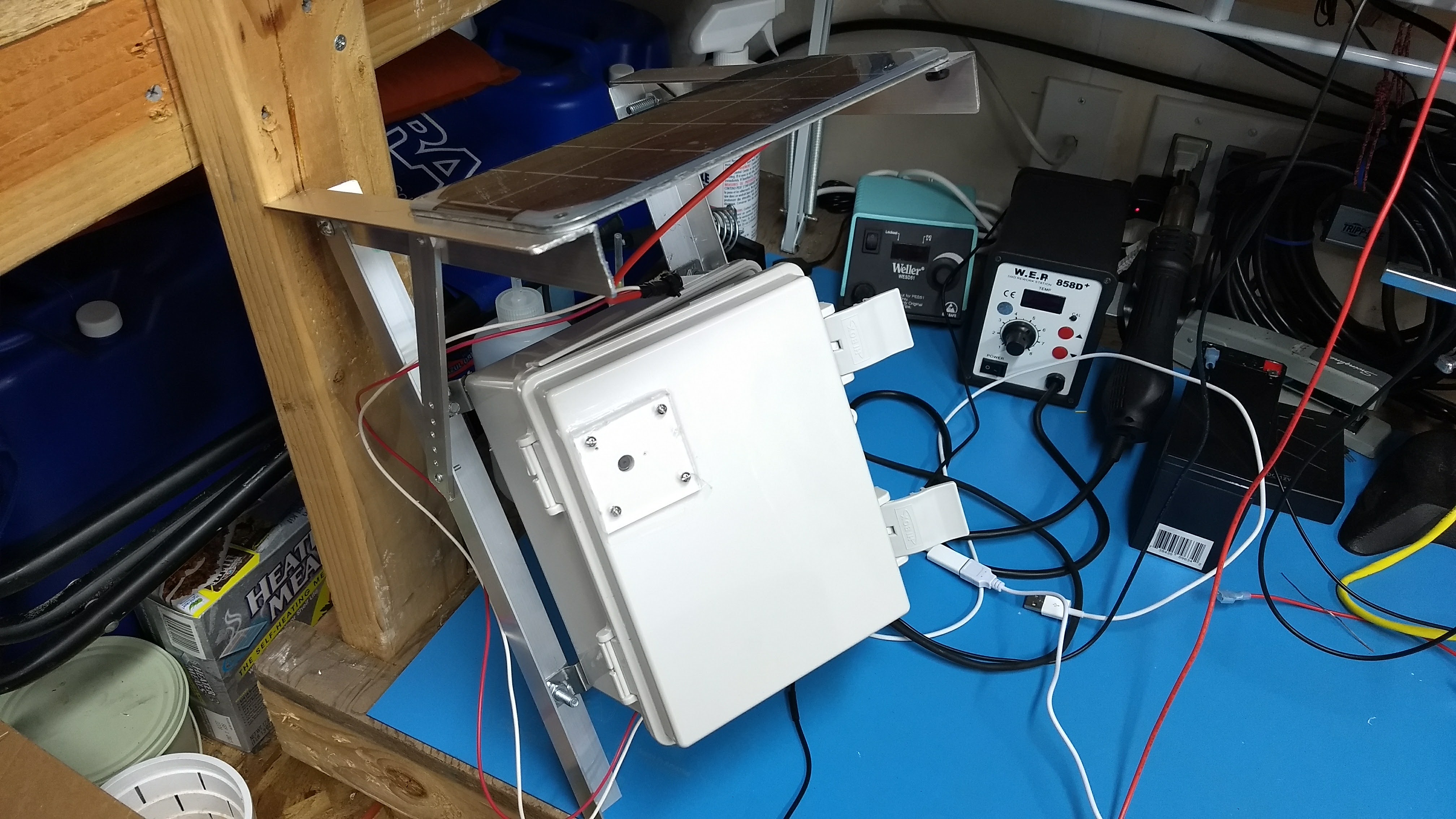
Probably the hardest part of this project for me was figuring out how to do it physically. Getting a proper waterproof box was easy. But how to mount the panel to the box, and then mount both of them to a tree or light stanchion was quite tricky for his non-mechanical engineer. I spent quite some time poking around Home Depot trying to figure out how to make it work. In the end, I bought a bunch of angle aluminum and start cutting and drilling and filing and screwing until I got something that more or less worked. It was a lot of effort, though, and doesn’t look very good. I really wished I could offload this part to someone more mechanically inclined than me.
Anyway, that’s it. We finally got the first camera deployed and after fixing a few bugs, it has started catching turkeys.
Does it Work?
You can see the system in operation here: https://skunkworks.lbl.gov/turkeycam. This is my “personal” dev server, and so it may be up or down or not showing pictures when you visit. Also, the second camera pictured is showing my office and will do so for the time being.
I still read Slashdot for my tech news (because I’m old, I guess) and came across this article, AI Training Algorithms Susceptible to Backdoors, Manipulation. The article cites a paper that shows how the training data for a “deep” machine learning algorithms can be subtly poisoned (intentionally or otherwise) such that the algorithm can be trained to react abnormally to inputs that don’t seem abnormal to humans.
For example, an ML algorithm for self-driving cars might be programmed to recognize stop signs, by showing it thousands of stop signs as well as thousands of things that are not stop signs, and telling it which is which. Afterwords, when shown new pictures, the algorithm does a good job classifying them into the correct categories.
But lets say someone added a few pictures of stop signs with Post-It notes stuck on them into the “non stop sign” pile? The program would learn to recognize a stop sign with a sticky on it as a non stop sign. Unless you test your algorithm with pictures of stop signs with sticky notes on them (and why would you even think of that?), you’ll never know that your algorithm will happily misclassify them. Et voila, you have created a way to selectively get self driving cars to zip through stop signs like they weren’t there. This is bad.
What caught my eye about this research is that the authors seem not to fully grasp that this is not a computer problem or an algorithm problem. It is a more general problem that philosophers, logicians, and semiologists have grappled with for a long time. I see it as a sign of the intellectual poverty of most programmers’ education that they did not properly categorize this issue.
Everyone has different terms for it, and I don’t know jack about philosophy, but it really boils down to:
Can you know what someone else is thinking?
Can you know how their brain works?
Can you know they perceive the same things you perceive the same way?
You can’t.
Your brain is wholly isolated from the brains of everyone else. You can’t really know what’s going on inside their heads, except so much as they tell you, and for that, even if everyone is trying to be honest, we are limited by “language” and the mapping of symbols in your language to “meaning” in the heads of the speaker and listener can never truly be known. Sorry!
Now in reality, we seem to get by. if someone says he is hungry, that probably means he wants food. But what if someone tells you there is no stop sign at the intersection? Does he know what a stop sign is? Is he lying to you? How is his vision? Can he see colors? What if the light is kinda funny? All you can do is rely on your experience with that person’s ability to identify stop signs to know if he’ll give you the right answer. Maybe you can lean on the fact that he’s a licensed driver. However, you don’t know how his wet neural net has been trained by life experience and you have to make a guess about the adequacy of his sign-identification skills.
These deep learning algorithms, neural nets and the like, are not much like human brains, but they do have this in common with our brains: they are too complex to be made sense of. That is, we can’t look at the connections of neurons in the brain nor can we look at some parameters of a trained neural network and say, “oh, those are about sticky notes on stop signs. That is, all those coefficients are uninterpretable.
We’re stuck doing what we have done with people since forever: we “train” them, then we “test” them, and we hope to G-d that the test we gave covers all the scenarios they’ll face. It works, mostly, kinda, except when it doesn’t. (See every pilot-induced aviation accident, ever.)
I find it somewhat ironic that statisticians have worked hard to build models whose coefficients can be interpreted, but engineers are racing to build things around more sophisticated models that do neat things, but whose inner workings can’t quite be understood. Interpreting model coefficients is part of how how scientists assess the quality of their models and how they use them to tell stories about the world. But with the move to “AI” and deep learning, we’re giving that up. We are gaining the ability to build sophisticated tools that can do incredible things, but we can only assess their overall external performance — their F scores — with limited ability to look under the hood.
Over the past couple of months, in stolen moments and late night coding sessions, I’ve quietly been inventing a little piece of ham radio gear intended to facilitate using one’s radio remotely.
I thought it would be a good way to try my hand at designing a useful product, from start to finish, including complete documentation, packaging, etc.
I posted about it to a few ham radio forums and it turned out nobody was interested, so instead of making a product, I’m just throwing it up on github for people to ignore forever.