I’ve been interested in energy efficiency for a long time. A big part of understanding energy efficiency is understanding how devices use power, and when. Because of that, I’ve also long wanted an AC power meter. A cheap one. A decent one. A small one.
What is an AC Power Meter
An AC power meter is an instrument that can tell you how much juice a plug-load device is using. The problem is that measuring AC power is a bit tricky. This is because when dealing with AC, the current waveform that a device draws does not have to be in phase with the voltage. A load can be inductive (lagging) or capacitive (leading), and the result is that the apparent power (Volts RMS * Amps RMS) will be higher than the real power. It gets worse, though. Nonlinear loads, like switch-mode power supplies (in just about everything these days) can have current waveforms that literally have no relation to the voltage waveform.
As a result, the way modern AC power meters work is to sample the instantaneous current and voltage many times a second, in fact, many times per 60 Hz AC cycle, so that the true power can be calculated by calculating the “scalar product” of the voltage and current time series. From such calculation, you can get goodies like:
- Real power (watts)
- Apparent Power (VA)
- Imaginary/Reactive Power (VAR)
- phase angle
- power factor
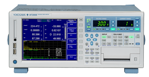
Instruments that do this well are expensive. For example, this Yokogawa WT3000E is sex on a stick as far as power meters go, but will set you back, I think more than $10k. I used one when I was at Google, and it was a sweet ride, for sure.
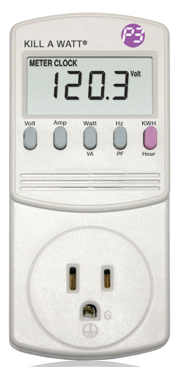
On the other hand, you can get a Kill-A-Watt for $40. This is cheap and functional, but is not capable of logging data, and is totally uncalibrated. They claim 0.2% accuracy, though? My experience with them says otherwise.
Over the years I’ve built a couple of attempts at a power meters. One used a current transformer and a voltage transformer going into the ADCs of an Arduino. It sort of worked, but was a mess. Another time, I built a device that used hall-effect sensors to measure current, but I didn’t measure voltage at all. This really couldn’t measure power, but you could get an indicative sense from it.
Let’s Do This – Hardware Design
So, a few months ago, I resolved to build a proper power meter. I did a search for chips that could help me out, and lo and behold, I came across several “analog front end” chips that have all the circuitry you need to measure AC power. They do the analog to digital conversion, all the math, and give you a simple digital interface where you can query various parameters.
I settled on the Atmel ATM90E26. Reasonable basic accuracy of 0.1% built on 16b analog-to-digital converters, and best of all, about $2 in quantity 1. Furthermore, they have an app note with a sample design, and it seemed simple enough.
So I started designing. Unfortunately, I had various conflicting goals in mind:
- Safety: like the McDLT, I want the hot to stay hot and the cool to stay cool. This means total isolation between the measurement side and the control side.
- Small, so it can be put inside a small appliance.
- A display, so I could read power data directly
- An interface to a Raspberry Pi so that I could log to a μSD card, or send it via WiFi to the Internet
- A microprocessor of its own to drive the display and do any real-time processing needed
- An internal AC to DC power supply so that the device itself could be powered from a single AC connection.
- Ability to measure current by way of sense resistor, current transformer, or some combination of both.
- Ability to get reasonably accurate measurement of very small loads (like < 1W) so that I can make measurements concerning vampire power. One way to do this wile keeping precision, is to build a unit with a high value shunt resistor, which I can do if I’m rolling my own.
Some of these desires conflict with each other, and I made several iterations on the computer before making my first board. I ended up jettisoning the LCD and building the thing around the RPi Zero. This was primarily to make the board compact. If I wanted a display I could plug one into the Pi! I also initially went with an outboard AC/DC converter mostly because I just didn’t want to fuss with it.
Power and Isolation
In a device that’s intended to live inside a plastic box, I probably wouldn’t bother with isolation at all. The whole circuit could “ride the mains.” But because this is supposed to be a tinker-friendly board, I wanted to be able to touch the RPi without dying. Usually, this is done with something simple like optoisolators to provide galvanic isolation for data signals. But this board presented another challenge. The power measurement chip needs to be exposed to the AC (duh, so it can measure it) but it also needs DC power itself to operate.
How to power the chip and maintain isolation? This could be done with a simple “capacitive dropper” supply (simple, inefficient, sketchy), or with an isolated DC-to-DC supply (pricey and or fussy), but when I added up the optoisolators I’d need plus the DC-DC supply, I realized that a special purpose chip would be nearly cost effective and would be a lot less fuss. So I chose the AduM5411, a nifty part from Analog Devices that can forward three digital signals in one direction, one digital signal in the other direction, and provide power across the isolation barrier. And it was only like $6.
Only problem is, the AduM5411 is so good it is pure unobtanium. I’m not even sure the part really exists in the wild. So I switched to the Texas Instruments ISOW7841, a very similar part in all respects, except for the fact that it costs $10. This is the most expensive part in my BOM by far. But I have to admit, it is super easy to use and works perfectly. (As an aside, these chips do not work on optical principles at all, but on tiny little transformers being driven at high frequency. Kind cool.)
Okay, so the AC/hot part of the board is powered from the DC side of the board. But how is the DC side powered? In the first iteration, I did it from a USB connector via a 5V wall-wart.
Current Measurement
In order to measure power, the measurement chip needs to be able to measure the voltage and current, simultaneously and separately. Voltage is pretty easy. Just use a resistor network to scale it down so you don’t blow up the ADC. Current can be done one of two ways. One is to measure the voltage drop across a calibrated resistor. The resistor obviously needs to be able to handle a lot of current and it will have to be a small value to keep the voltage drop reasonably, or else the device you’re measuring will be unhappy. The current sense resistor should also have a low temperature coefficient, so that its value doesn’t change much as it warms up.
The other approach is to use a current transformer. CTs are nice in that they provide isolation, but they are large and cost a few bucks compared to the few pennies for the resistors. I did an iteration with space for a CT on the board, but later punted on that. I did leave a place where an external CT can be plugged into the board. I may never use it, though.
The Microcontroller
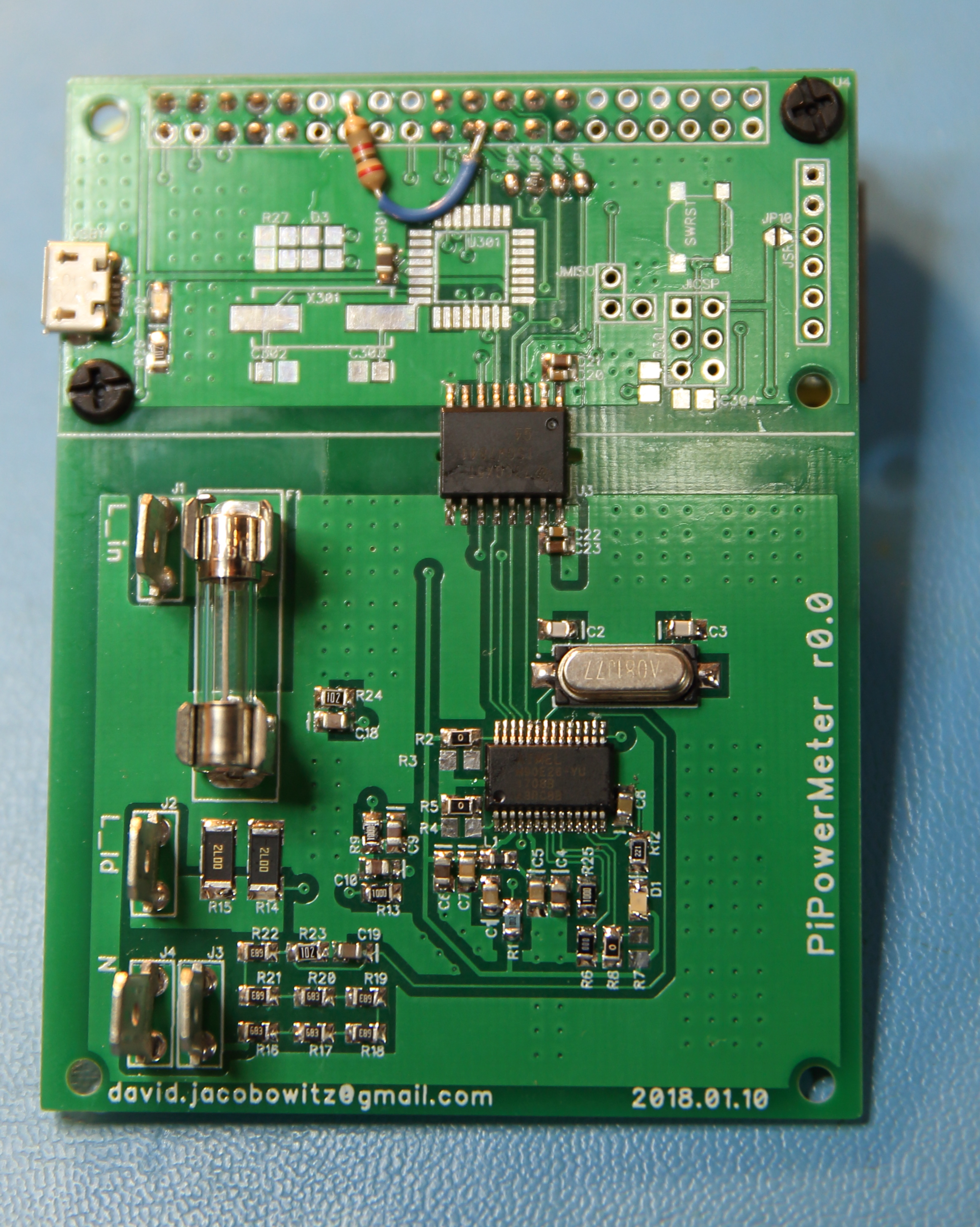
In this design, an Atmega 328p microcontroller sits between the Pi and the ATM90E26. It is connected to the ATM90E26 by a SPI bus and to the Pi by an I2C bus. Originally, I had thought the Atmega would have to poll the power chip frequently and integrate the total energy, but that was because I did not read the ATM90E26 data sheet closely enough. It turns out that chip can does all the math itself, including integrating energy, and so the processor was just sitting there doing conversion between I2C and SPI. I honestly could not come up with anything else useful for the Atmega to do.
Anyway, the good news was that this design worked straight away — hardware wise, though it turned out to be more work than I wanted to get the Atmega to do the I2C/SPI forwarding reliably. And I didn’t even need it.
Ditch the processor!
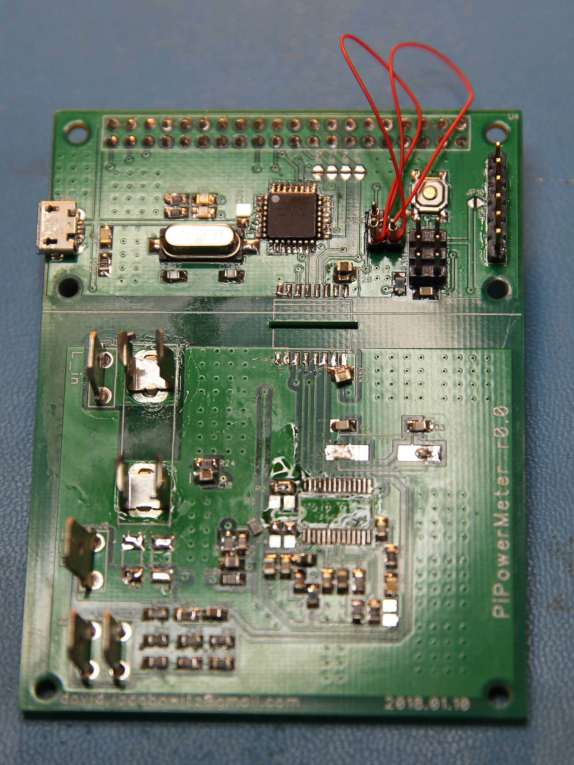
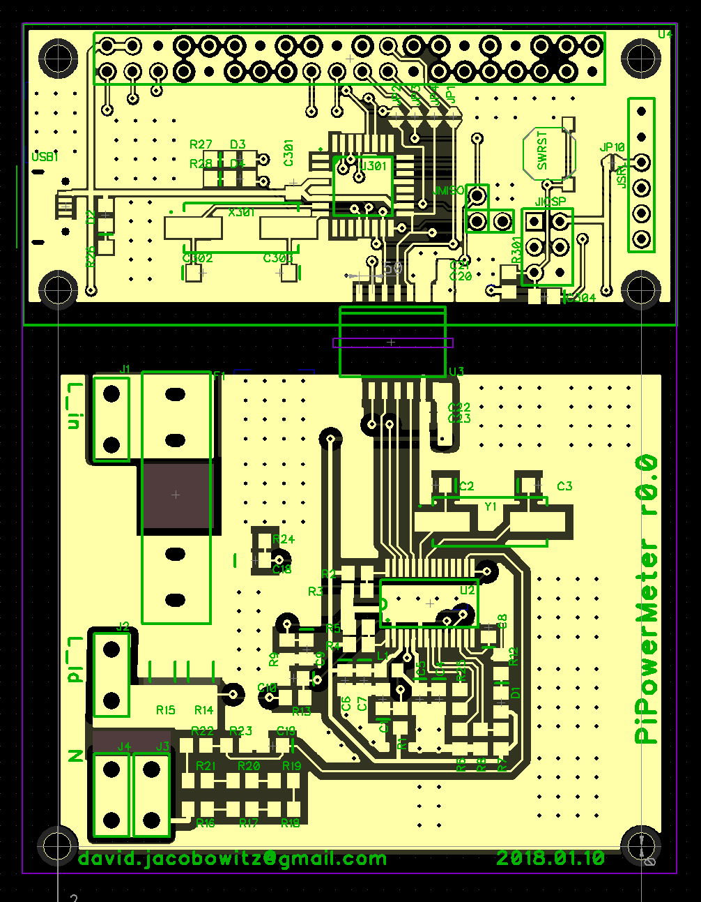
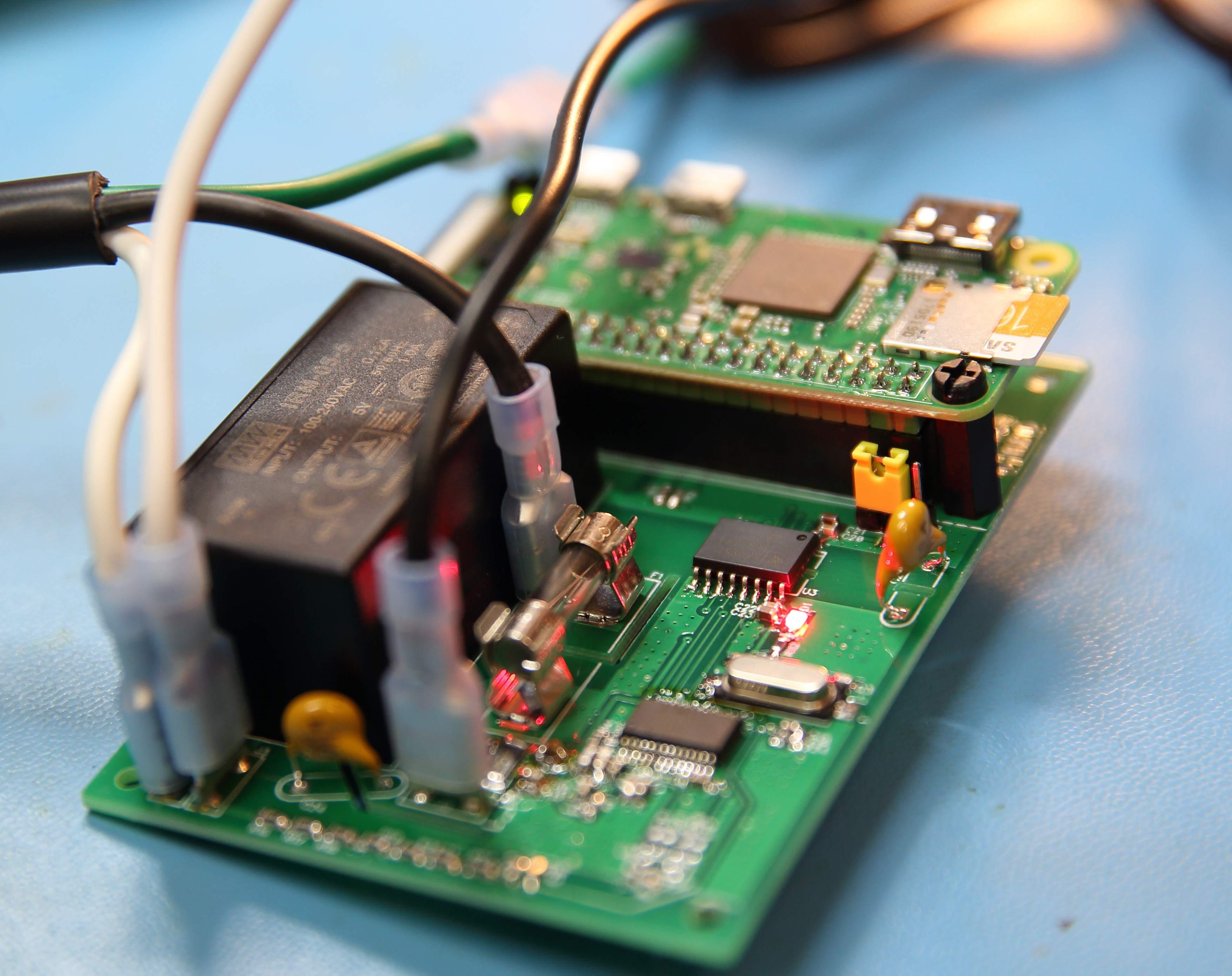
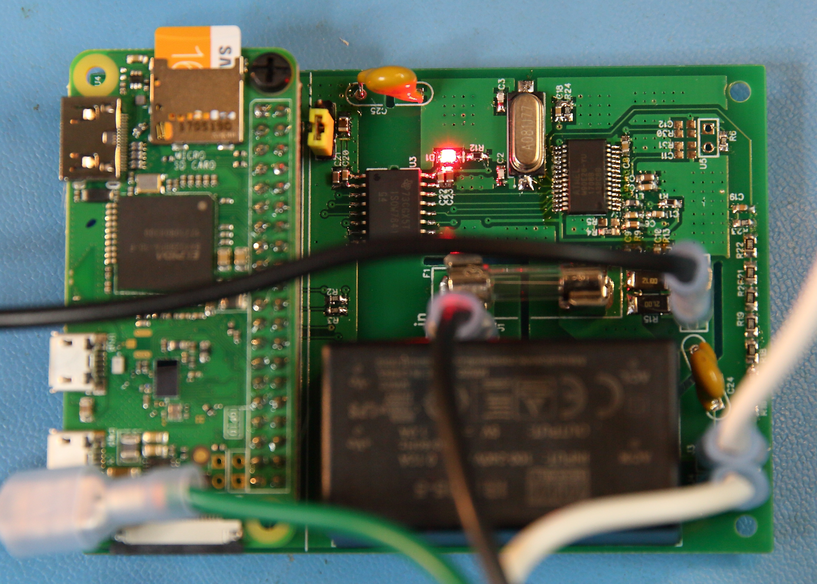
So, using the same PCB, I made some simple hacks to bring the SPI bus pins from the measurement chip to the RPi header. I also had to add a voltage divider so that the 5V MISO signal would not destroy the not-5V-tolerant MISO pin on the RPi. The hacked board looked like this.
The RPi communicates with the power measurement chip through the TI isolation chip, and des so reliably and much faster than I2C, so I was glad to realize that I didn’t need that intermediary processor in the mix at all.
This board could be pressed into service as it was, but it has a couple of issues:
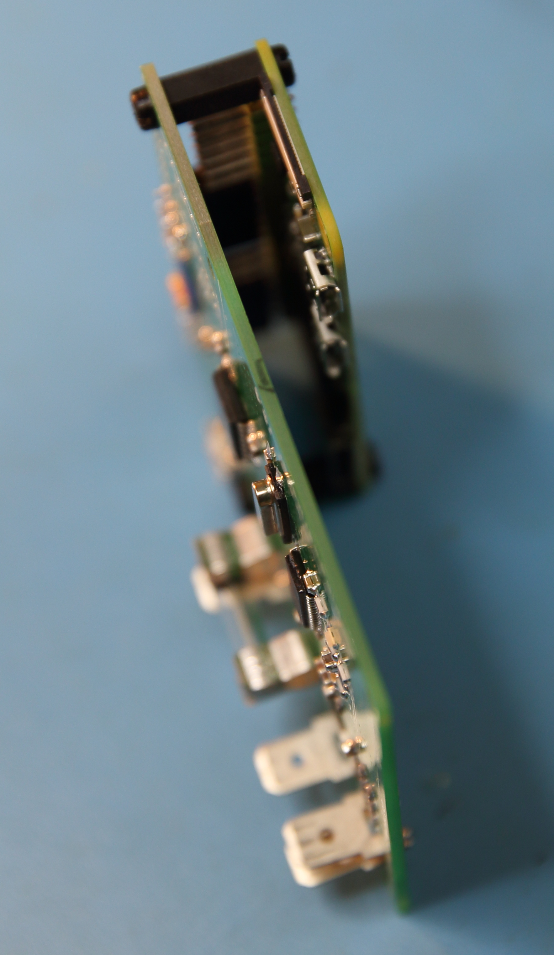
- First, the orientation of the Pi relative to the board saves a bit of space, but does so at the cost of having all the Pi connectors face down towards the “hot” side of the board.
- Second, powering the DC side of the board from the USB jack proved more annoying to me than I had anticipated. It really just bugs me to have to plug an AC measuring device into a separate wall-wart. So I knew I’d design in a PSU. I chose a MeanWell IRM-05-05 PCB mount 5V PSU.
- Third, this board lacked cut-outs to provide extra creepage for high voltage parts of the board that would be (or could be) at high relative voltage from each other. I think the distances were probably adequate, and it’s not like I was going for a UL listing or anything, but I still wanted slots.
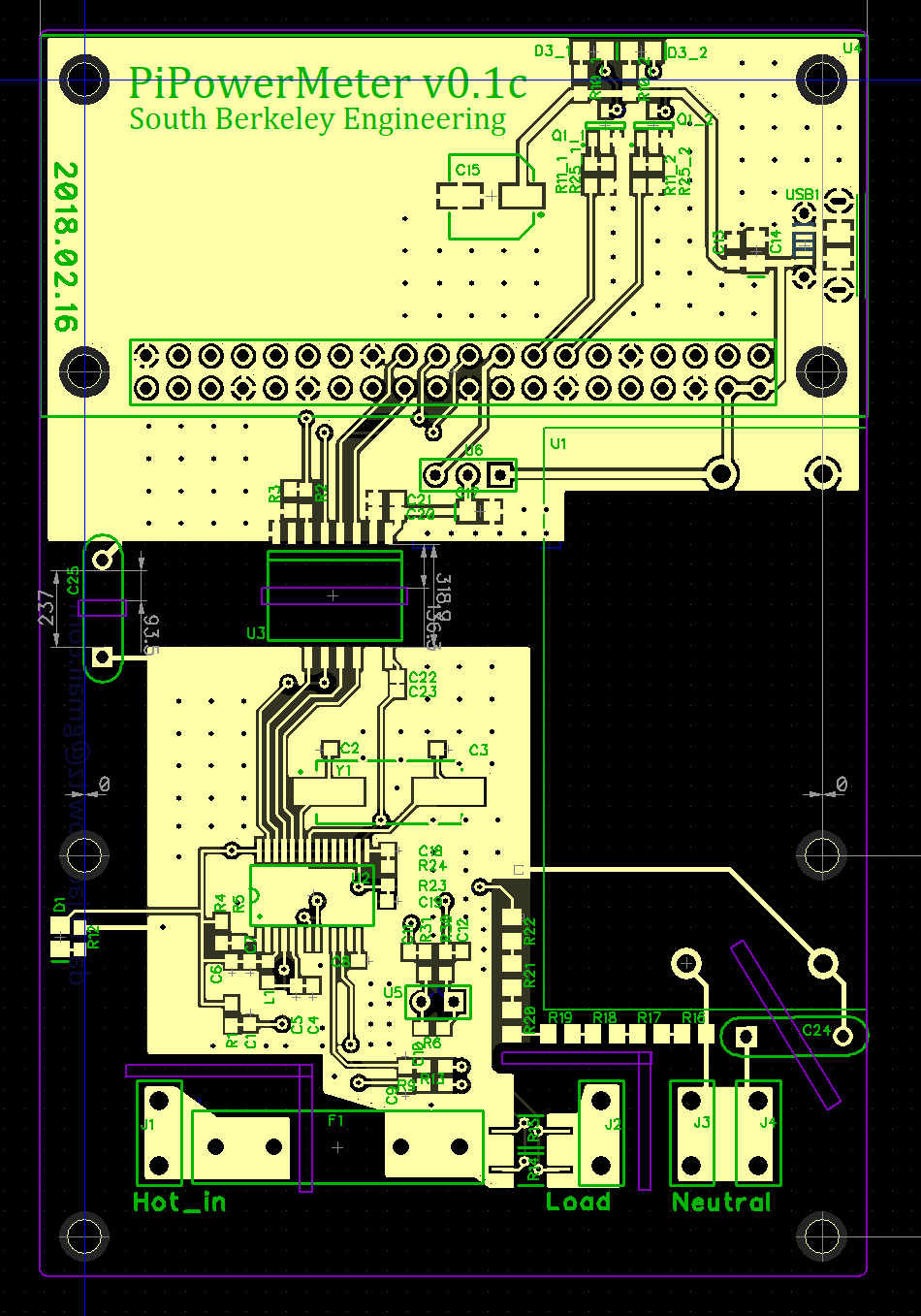
So, I redesigned the board and waited a month for them to arrive from China even though I payed for expedited shipping. The new board looks like this. Some of the space where the processor had gone I replaced room for LEDs, in case I want to blink some lights.
So that is just about it for the hardware.
One last spin.
As it turns out, I will spin this board one more time. The main reason is that I want to expand it a bit and move the mounting holes to match up with a suitable enclosure. I will probably use a Hammond RP-1127 — it’s exactly the right width for an RPi.
The other reason is that someone showed me how to redraw the pads for the current sense resistors to make a “quasi” kelvin connection.
The way the current measurement is to measure the current across the sense resistor. This resistor is reasonably accurate and temperature stable, but the solder and copper traces leading to it are not, and current flowing in them will cause a voltage drop there, too. This drop will be small, but the drop across the 0.001 Ω sense resistor is small, too! So, to get the most accurate measurement, I try to measure the voltage drop exactly at the resistor pads, preferably with connections to the resistor that have no current in them. This i what Kelvin connections are.
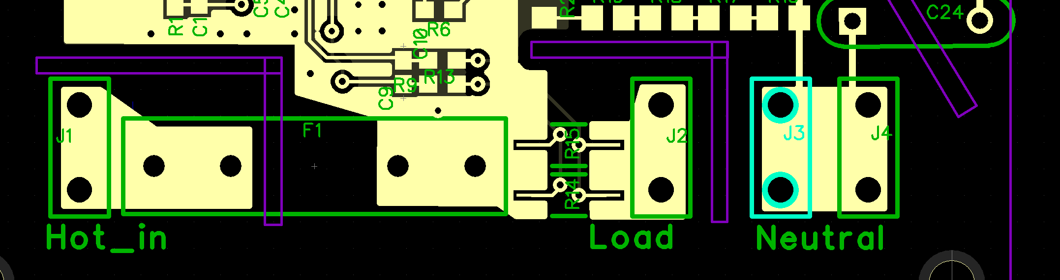
In the case below, I achieve something like this by splitting the pads for the resistor into three pieces. The top and bottom conduct test current across the resistor, and a small, isolated sliver in the middle measure the voltage. There is no current in that sliver, so it should have no voltage drop.
The result should be better accuracy and thermal stability of the current measurements. The Kelvin connection for the current measurement looks like this. The sense resistors go betwen the right terminal of the input fuse and the tab marked “load.” The resistor landing pads are split and a separate section, in which no current will flow is for the voltage measurement.
Calibration
An instrument is only as good as its calibration, and I needed a way to calibrate this one. Unfortunately, I do not have the equipment to do it properly. Such equipment might be a programmable AC source, a high-accuracy AC load, and perhaps a bench quality power meter. What I do have access to are reasonably accurate DMMs (Fluke 87V and HP 34401A). The former is actually in cal, the latter, well, a million years ago, I’m sure.
I calibrated the voltage by hooking the unit up to the AC mains in my house and measuring the voltage at the terminals and adjusting a register value until the reported voltage matched my meter. For current, I put a largeish mostly non-inductive load on the system (Toast-R-Oven) and measured the current with my DMM and adjusted the register until the current matched.
Calibrating power is harder, and I really don’t have the right equipment to do it properly. The ATM90E26 allows you to also set up an energy calibration separate from the voltage and current measurements, and I think it is their intention that this be done with a known load of crappy power factor. But I don’t have such a load, so I sort of cribbed a guess at the energy calibration based on my voltage and current measurements of the toaster oven. This probably gets me close for resistive loads, but is not good enough for loads with interesting power factor. Unfortunately, the whole point of an AC power meter is to get this right, so in this important way, my meter is probably importantly compromised.
The result is that this is probably not a 0.1% instrument, or even a 1% instrument, but I guess it’s good enough for me… for now. I’ll try to think of ways to improve cal without spending money for fancy equipment or a visit to a cal lab.
Okay, so now about software
One of the reasons I like working with the Raspberry Pi, is that I get a “real”, and “normal” linux operating system, with all the familiar tools, including text editors, git, and interpreted programming languages like python. Python has i2c and SPI libraries for interacting with the the RPi hardware interfaces, so it was not a big deal to create a “device driver” for the ATM90E26. In fact, such a device driver was pretty much just an exercise is getting the names of all the registers and their addresses on one page. One nice thing my device driver does is convert the data format from the ATM90E26 to normal floats. Some of the registers are scaled by 10x or 100x, some are unsigned, some are signed two’s complement, and some have a sign bit. So the device driver takes care of that.
I also wrote two sample “applications.” The first is a combination of an HTTP server app and a client app running on the meter that forwards info to the server, and the server can display it in a web browser.
The other application is simpler, but in a way, more useful: I have the RPi simply upload samples to a Google Sheet! It’s very satisfying to plug in a logger and then open a Google Sheet anywhere and see the data flowing in every few seconds.
Results
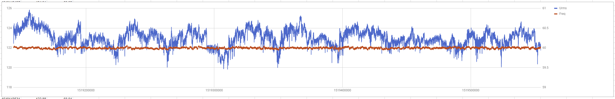
So far, I’ve been able to things like log the voltage and frequency of the mains every second for the past week. I plan to deploy a few of these around the house, where I can see how various appliances are actually used.
Here’s a picture of the voltage and frequency as measured in my work shed for most of a week starting on 2/20/2018. The data are in 5 second intervals.
Design Files
I have not decided if I’m going to open-source this design yet, so I’m going to keep the hardware files to myself for the time being. There is also a liability concern, should someone take my stuff and manage to burn his house down or kill himself.
But you can see my github repo with the software. Not too much documentation there, but I think the file atm90e26.py should be reasonably self-explanatory as a simple Python-based wrapper for an ATM90E26 connected to a Pi via SPI.
Future Directions
- Better calibration
- Better WiFi performance when device is inside a metal appliance (external antenna)
- Switchable current ranges. Maybe with relays swapping in difference sense resistors.
I need to know about how you measure the current ? Which current sensor resistors you used on pcb,
I don’t remember the specific resistors. They were 1% low tempco 1206 chip resistors. Maybe 2 milliohm. I used two in parallel.
The exact calibrated value isn’t so important because you can calibrate the device. There tempco is important, even though the values are low enough that i don’t expect significant self heating at the current levels my unit is defined for.
This is excellent, thanks for the in-depth breakdown of your design! Have you ever come up with a better way to calibrate for power? I hope you decide to open source the hardware design, too. 🙂
I might release the design. I’m pretty sure I do not plan to commercialize it. Because it deals with mains power, I do fear that the design should only be implemented by folks who know what they are doing.
So far, it has been accurate for my needs without any more sophisticated calibration. I think the right way to do this in the future is to create some test loads, perhaps using a transformer and resistor, and cap and resistor, then characterize those using a better instrument, and then use those to calibrate this instrument. This, I think avoids the need for some very sophisticated controllable impedance load.
Hello Dave,
Great project!
I really think this is the easiest/cheapest way to calibrate.
I work for a small company producing transformers for PCB mount and this gave me an idea to create a test station for our transformers. Currently we are using a set of 4 Mastech multimeters – one for the input voltage, one for the no load current and two for the separate output voltages (if needed) and a guy manually checking all that and deciding if there is a fault/error. In my opinion a way better way for testing is updating your design with two more low-side voltage meters and checking the values to a table with predefined sets and for example bringing PASS/FAIL report on a display (it could also be a LED or something, but I think the idea with display is more appropriate, because it can show what is the reason for fail).
Can you please, give some more info on your hardware design so I don’t need to invent the wheel again. 🙂